Rockwell Automation 20D PowerFlex 700H/S Frame 12 Replacement Power Structure User Manual
Page 7
PowerFlex® 700S and 700H Frame 12 Replacement Power Structures
7
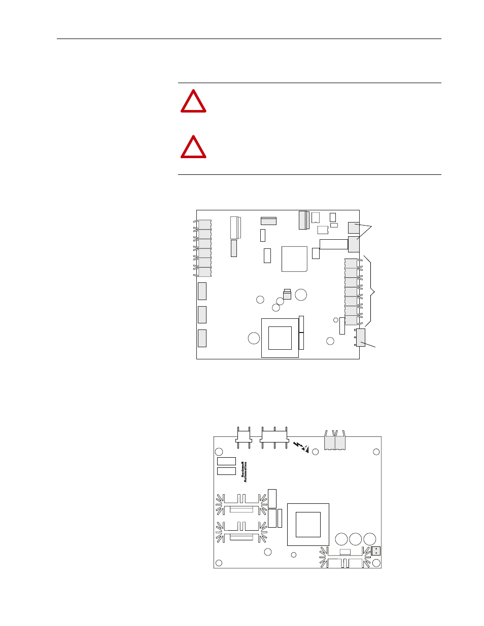
4. Carefully disconnect the fiber-optic cables from sockets along the front
of the ASIC board, and carefully set them aside.
5. Disconnect the other cables from the sockets on the front of the ASIC
board, and set them aside.
6. If you are replacing a power structure on a PowerFlex 700S drive,
disconnect the cable from connector J8 and the fiber optic connections,
J4 and J5, from the Power Supply Voltage Feedback board on the power
structure in the left-hand enclosure.
!
ATTENTION: Hazard of permanent eye damage exists when
using optical transmission equipment. This product emits intense
light and invisible radiation. Do not look into fiber-optic ports or
fiber-optic cable connectors.
!
ATTENTION: The sheet metal cover and mounting screws on
the ASIC Board located on the power structure are energized at
(-) DC bus potential high voltage. Risk of electrical shock, injury,
or death exists if someone comes in contact with the assembly.
H11
H12
H13
H8
H9
H10
X6
X9
X15
X3
X4
X5
X2
X1
H4
H5
H6
H1
H2
H3
H7
X26
X11
Fiber Optic ports
Connects to X50
terminal block for
pre-charge circuitry on
DC Input drives
Connects to DC Bus
J4 J5
J8