Figure 3 700s connections, Asic board #1, Board #2 feedback – Rockwell Automation 20D PowerFlex 700H/S Frame 12 Replacement Power Structure User Manual
Page 17
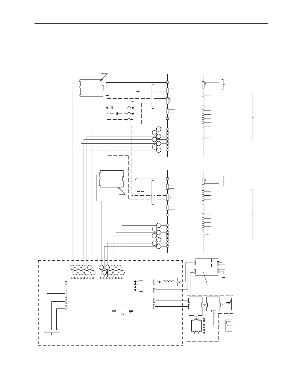
PowerFlex® 700S and 700H Frame 12 Replacement Power Structures
17
Step 9: Connecting the
Power Structure to
Components on the Drive
You must connect the power structure to control components on the control
frame. If the drive has DC input, you must also connect the precharge
circuit.
Figure 3 700S Connections
Fiber Optic
1
2
3
4
5
6
7
X3
X2
X6
ASIC
Board #1
X9
X15
Charge
Relay
Fan
Control
25
26
21
22
23
1
2
3
W/T3 Phase from Pwr Strctr
V/T2 Phase from Pwr Strctr
U/T1 Phase from Pwr Strctr
DC+ From Power Structure
Star Coupler Fiber Optic Interface Board
J18
J15
J28
J13
-12 V
+12 V
+24 V Iso
+5V
Fiber Optic
NET B
DPI Assembly
20-VB00601
DPI
Option
Comm
Interface
DPI
2
9
J16
J4
X4
X3
X2
NET A
PORT
MOD
20
PWR
STS
9
HIM
X1
J2
J3
J1
9
Bezel
External
DPI
HIM
20-HIM-A3
Example:
Door
HIM
Power Supply Voltage Feedback Board
Supply
Power
2
J7
J6
J5
J4
J5
+24V
J8
J2
80 W
-W
-V
-U
-DC+
-DC-
J1
DC- From Power Structure
2
LED
DPI
Status
X10
H1
H2
H3
H4
H5
H6
H7
+24V
0EVA
Fiber
9
8
8
9
24V Power
X4
X5
H8
H11
H12
H9
H10
X11
X600
H13
X26
1
2
+24VDC
DC-
X1
DC-
DC+
H903
H901
H900
H902
X900
6
X3
H7
H6
H5
H4
H3
H2
H1
X10 24V Power
1
2
23
22
+24VDC
DC-
X1
Relay
Charge
H13
X11
X600
Fan
Control
H10
H11
H12
H9
X5
H8
X4
ASIC
Board #2
H902
H901
H900
H903
X900
X15
26
21
25
0EVA
+24V
X9
X26
6
2
X6
X2
3
1
3
3
J1
J2
J17
J3
J27
From DC Bus
in Power Circuitry
To Gate Driver Board X14
To Gate Driver Board X13
To Gate Driver Board X15
To Gate Driver Board H4
To Gate Driver Board H5
To Gate Driver Board H6
To Gate Driver Board H7
To Gate Driver Board H8
To Gate Driver Board H9
To Rectifying Board X13
DC-
DC+
From DC Bus
in Power Circuitry
To Gate Driver Board X14
To Gate Driver Board X13
To Gate Driver Board X15
To Gate Driver Board H4
To Gate Driver Board H5
To Gate Driver Board H6
To Gate Driver Board H7
To Gate Driver Board H8
To Gate Driver Board H9
To Rectifying Board X13
1
2
3
4
5
6
7
1
Fiber Optic
2
3
4
5
6
7
Board #1
Feedback
Board #2
Feedback
External 24V DC
1=24V
3=Common
(75W min)
Fan
Power
1
2
3
4
5
7
6
T
1
2
3
4
5
7
6
T
To Main Control Board
700S Phase II Control Assembly
J14
J12
J11
J10
J9
J8
J24
J25
J23
J22
J21
J20
J19
To Left Fan X8
On P
o
w
e
r Str
ucture #1 (Left)
On P
o
w
e
r Str
ucture #2 (Right)
To Left Fan X8
CR1
M
CR1
CR2
M
M
M
Sample Pre-Charge
Connection Shown
in Dashed Lines
2
1
4
3
2
1
4
3
X50
PS #2
X50
PS #1
External Wiring
Shown as Dashed
Lines
2
Common Mode
FIlter Board
J5
J1