Step 8: installing the new power structure, L1 l2 l3 – Rockwell Automation 20D PowerFlex 700H/S Frame 12 Replacement Power Structure User Manual
Page 16
16
PowerFlex® 700S and 700H Frame 12 Replacement Power Structures
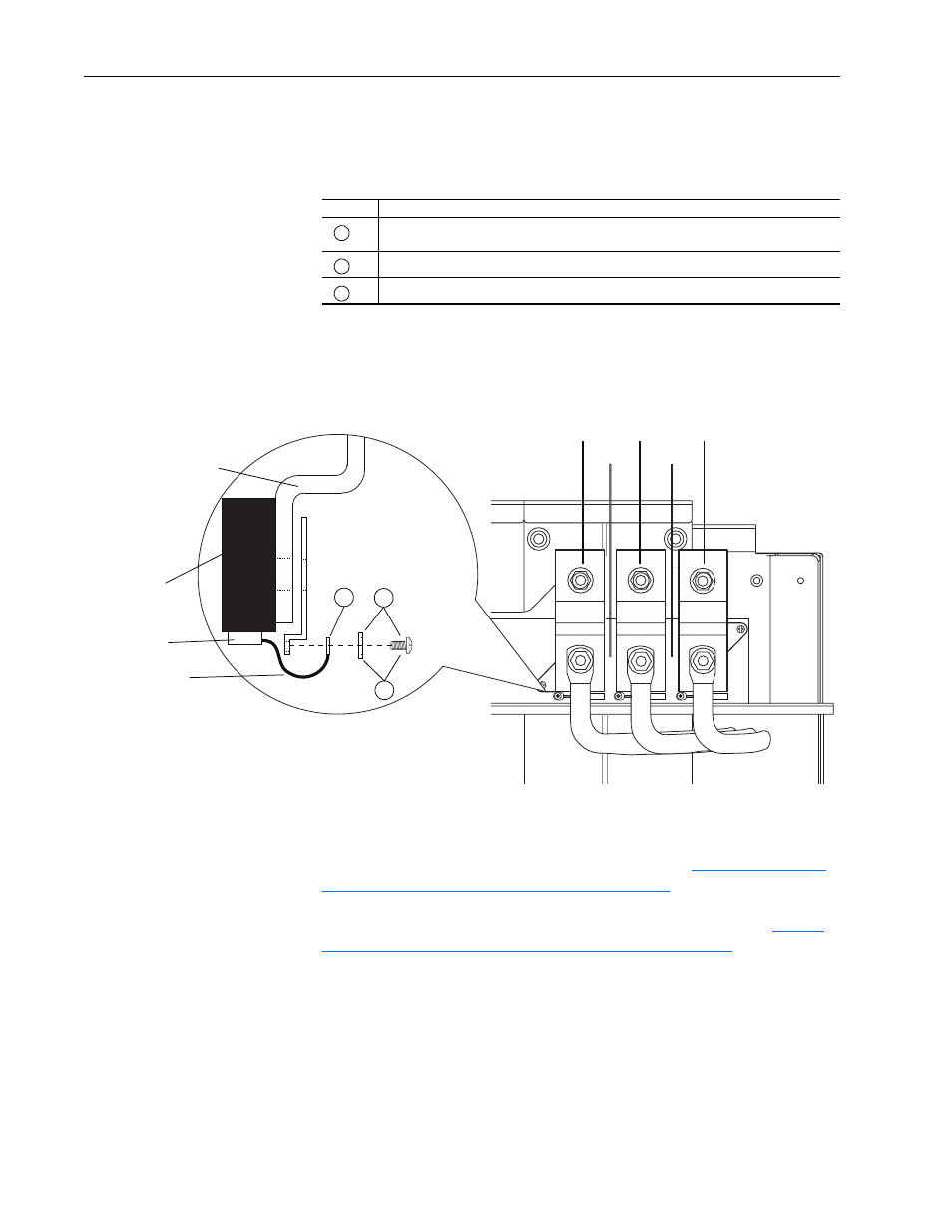
Disconnect the Small Capacitors from the Input Terminals
Follow the lettered steps below to disconnect the small capacitors from the
input terminals:
Important: Do not re-install the capacitor leads.
Step 8: Installing the New
Power Structure
Install the new power structure in the reverse order of
the Old Power Structure from the Drive" on page 8
and make the motor,
ground, input power and Power Supply Voltage Feedback board (for
PowerFlex 700S installations) connections in the reverse order of
"Preparing the Old Power Structure for Removal" on page 6
Task
Description
Remove the screws and lock washers that secure each of the three capacitor supply wires
to the input power terminals.
Insulate the capacitor leads and leave disconnected.
Install and tighten the screws and lock washers only.
A
B
C
L1
L2
L3
A
B
C
Important: It is not necessary to remove the power
wiring from the terminals in order to
insulate the capacitor leads.
Capacitor
Insulator
Capacitor lead
Input power terminal