D.2.5 parameter accessing routine, D-11, Slc ladder logic examples – Rockwell Automation MD65 Profibus Communication Card User Manual
Page 97
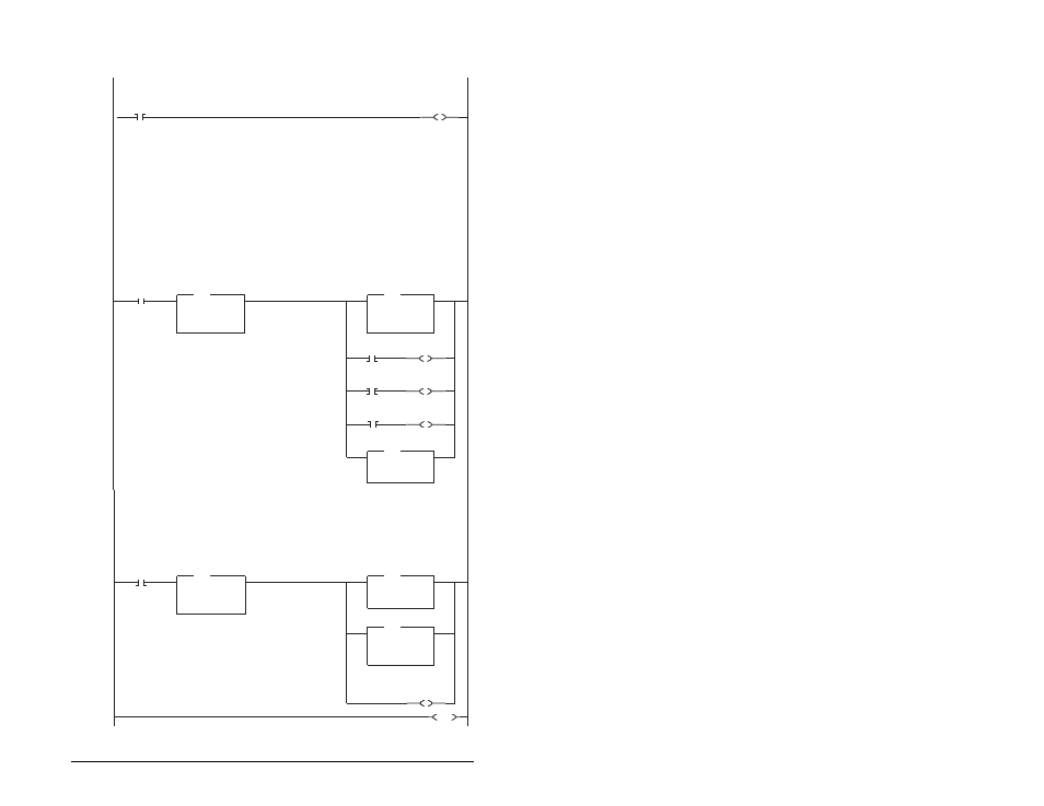
SLC Ladder Logic Examples
D-11
D.2.5 Parameter Accessing Routine
r
This section of the outine is only needed if the application needs to perform Parameter Protocol Reads or Writes to Station 2.
On power-up, initialize the Parameter Protocol routine.
0
S:1
15
First Pass
U
B3:19
0
Par Prot
Messaging
Request
This circuit utilizes the Para meter Protocol. A REQUEST to the Profibus adapter is processed only one at a time,
and after each RESPONSE from the adapter a zero must be sent and received to 'handshake' before the next
REQUEST/RESPONSE transaction can take place. For example:
Send a parameter read request --> Receive a parameter read response --> Send a "0" --> Receive a "0" --> [Transaction complete]
If the RESPONSE PCA Word 1 (N10:6) is "0", then a REQUEST can be initiated
.
Elsewhere in the user program these words must be loaded with message data prior to initiating the REQUEST.
N7:10 = RC = the operation to be performed ("1" = Read, "2" = 16-bit Write)
N7:11 = PNU = the parameter number to read or write
N7:12 = Subindex = the MDIport # ("0" = Station 0, "1" = Station 1, "2" = Station 2, "5" = MDCOMM-PBUS, etc.)
N7:13 = PVA #1 (the parameter value (high word)) - only used when writing parameters
N7:14 = PVA #2 (the parameter value (low word)) - only used when writing parameters
The four Parameter Protocol Words set up in the scanner are used to perform the Parameter Protocol:
N20:6 = contains RC (the operation to be performed) and PNU (the parameter number to read or write) combined
N20:7 = Subindex (the MDIport #)
N20:8 = PVA #1 (the parameter value (high word))
N20:9 = PVA #2 (the parameter value (low word))
B3:19/0 is turned ON elsewhere in the program after a REQUEST message (N7:10-14) is loaded. This causes one
Parameter Protocol read or write to occur and B3:19/0 is turned OFF when the transaction is complete.
1
B3:19
0
Par Prot
Messaging
Request
EQU
Equa
Source A
N10:6
0<
Source B
0
0<
EQU
RESPONSE
PCA Word
MOV
Move
Source
N7:11
77<
Dest
N20:6
12304<
MOV
PCA Word
N7:10
0
RC bit 0
L
N20:6
12
PCA Word
RC bit 0
N7:10
1
RC bit 1
L
N20:6
13
PCA Word
RC bit 1
N7:10
2
RC bit 2
L
N20:6
14
PCA Word
RC bit 2
COP
Copy File
Source
#N7:12
Dest
#N20:7
Length
3
COP
IND Word
(Subindex)
N10:6 is the Response Parameter Access Word 1. It is <> 0 when a message has been received in response to a
message request. If the response is >= 7000 hex (28672 decimal), then the adapter is responding that an error has occurred.
In this case, the returned data in the response will contain a fault code and not the parameter value data.
The response message can be found at:
N7:20 = PCA Word = contains RC and PNU
N7:21 = Subindex = the MDIport # ("0" = Station 0, "1" = Station 1, "2" = Station 2, "5" = MDCOMM-PBU
S, etc.)
N7:22 = PVA #1 = the parameter value (high word)
N7:23 = PVA #2 = the parameter value (low word)
The PVA's will either contain parameter read data, echo the parameter write data or contain an error code if unsuccessful.
2
B3:19
0
Par Prot
Messaging
Request
NEQ
Not Equal
Source A
N10:6
0<
Source B
0
0<
NEQ
RESPONSE
PCA Word
COP
Copy File
Source
#N10:6
Dest
#N7:20
Length
4
COP
RESPONSE Message
PCA Word
MOV
Move
Source
0
0<
Dest
N20:6
12304<
MOV
PCA Word
U
B3:19
0
Par Prot
Messaging
Request
3
END