Slc ladder logic examples – Rockwell Automation MD65 Profibus Communication Card User Manual
Page 91
SLC Ladder Logic Examples
D-5
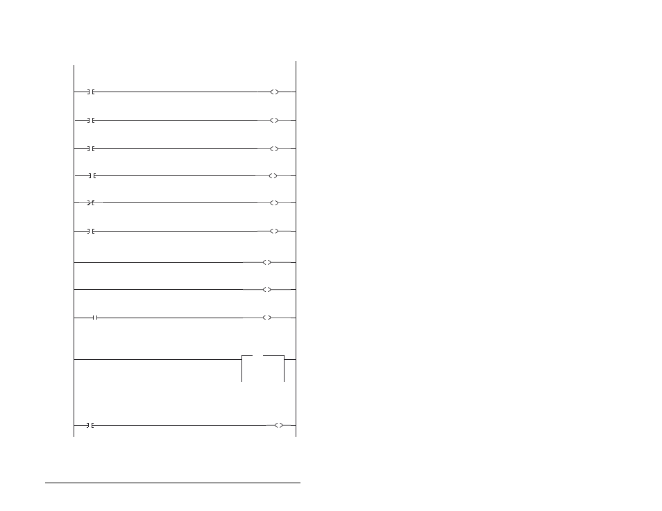
D.1.3 Drive 1 Control/Reference/Parameter Access
Routine
gi
Controlling the Lo c Command word in the drive. B3:21/* bits are controlled elsewhere in the user program.
0
B3:21
0
Station 2
Stop
Command
N20:6
0
Station 2
Logic Command
STOP
1
B3:21
1
Station 2
Start
Command
N20:6
1
Station 2
Logic Command
START
2
B3:21
2
Station 2
Jog
Command
N20:6
2
Station 2
Logic Command
JOG
3
B3:21
3
Station 2
Clear Faults
Command
N20:6
3
Station 2
Logic Command
CLEAR FAULTS
4
B3:21
4
Station 2
Reverse
Command
N20:6
4
Station 2
Logic Command
FORWARD
5
B3:21
4
Station 2
Reverse
Command
N20:6
5
Station 2
Logic Command
REVERSE
To control the speed reference over the Profibus, the three Reference Select bits (bits 14-12) need to have the values 011.
6
N20:6
12
Station 2
Logic Command
REFERENCE SELECT 0
7
N20:6
13
Station 2
Logic Command
REFERENCE SELECT 1
8
B3:21
5
"Never Closed"
N20:6
14
Station 2
Logic Command
REFERENCE SELECT 2
Station 2 Speed Reference
N19:7 is controlled elsewhere in the user program.
9
MOV
Move
Source
N19:7
314<
Dest
N20:7
314<
MOV
Station 2
Speed Reference
Write
This section of the routine is only needed if the application needs to perform Parameter Protocol Reads or Writes to Station 2.
On power-up, initialize the Parameter Protocol routine.
10
S:1
15
First Pass
U
B3:19
0
Station 2
Par Prot
Messaging
Request
The MD65 Speed Reference (parameter 38) needs to be set to 5 ("RS485 [MDI] Port").