3 connecting the module to the network – Rockwell Automation MD65 Profibus Communication Card User Manual
Page 20
3-4
PROFIBUS Communications Module
Step 2.
Verify the Network Baud rate, which is set by the network
master and depends on cable length.
The MDCOMM-PBUS module uses the Auto-Baud and
supports the following different data rates: 9.6 kpbs, 19.2
kpbs, 45.45 kpbs, 93.75 kpbs, 187.5kpbs, 500 kpbs, 1.5
Mpbs, 3 Mpbs, 6 Mpbs, and 12 Mpbs.
The Auto-Baud function allows the module to recognize
the current baud rate and sets itself to the transmission
rate by the master automatically. After detecting the
correct baud rate, the baud rate that was found is
monitored continuously. Auto-Baud is always active.
Step 3.
Set the Byte Swap jumper J3, which determines the Intel
or Motorola (position SWAP) data format depending on
the corresponding PLC. See Figure 3.1.
Step 4.
Verify that the jumper J2 is in position “1X” for Single
Drive operation, or set J2 in “5X” for Multi Drive operation.
3.3
Connecting the Module to the
Network
Step 1.
Remove power from the drive.
Step 2.
Use static control precautions.
Step 3.
Remove the drive cover.
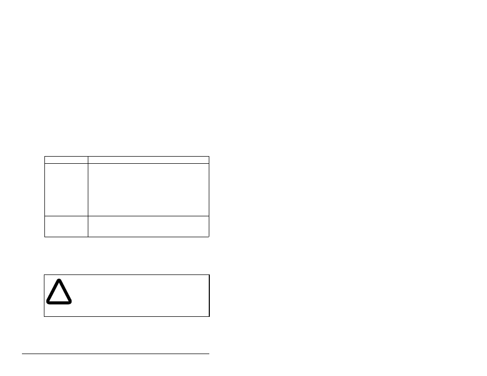
Table 3.3 – Jumper Settings
Jumper Setting
Description
Right position or
jumper missing
Sets the module for Single drive mode (default
setting) using a single drive connection.
Important:In this mode, connections to multiple
drives must be removed since all
powered and connected hosts will
respond to any message sent by the
module.
Left position
Sets the module for Multi-Drive operation mode
using up to 5 different drives. MDI peripherals do
not operate with the module in this mode.
!
ATTENTION: The drive may contain high voltages
that can cause injury of death. Remove all power
from the drive, and then verify power has been
removed before installing or removing a PROFIBUS
module. Failure to observe these precautions could
result in severe bodily injury or loss of life.