3 using logic command/status – Rockwell Automation MD65 Profibus Communication Card User Manual
Page 52
6-2
PROFIBUS Communications Module
The I/O image table will vary based on the configuration of the
Mode Jumper (J2) on the module and MDI I/O Cfg (parameter 11).
The image table always uses consecutive words starting at word 0.
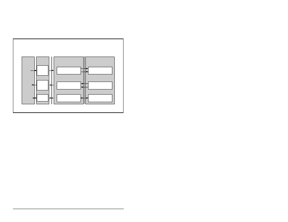
Figure Figure 6.1 illustrates an example of a drive I/O image (16-bit
words).
Single drive mode is the typical configuration, where one node
consists of a MD65 drive with a MDCOMM-PBUS module.
For Multi-Drive mode, where one node can consist of up to five
drives, refer to chapter 8, Using Multi-Drive mode.
6.3
Using Logic Command/Status
When enabled, the Logic Command/Status word is always word 0 in
the I/O image. The Logic Command is a 16-bit word of control
produced by the scanner and consumed by the module. The Logic
Status is a 16-bit word of status produced by the module and
consumed by the scanner.
This manual contains the bit definitions for compatible products
available at the time of publication in Appendix C, Logic Command/
Status Words. For other products, refer to their documentation.
Figure 6.1 – Single Drive Example of I/O Image
Controller
Scanner
Adapter
MD65 Drive
PROFIBUS
MDI
Output
Image
(Write)
Input
Image
(Read)
Message
Handler
Message
Buffer
0 Logic Status
1 Feedback
Logic Status
Feedback
Word and I/O
Message
Handler
0 Logic Command
1 Reference
Logic Command
Reference