D.2 multi-drive example, D.2.1 main routine, Slc ladder logic examples – Rockwell Automation MD65 Profibus Communication Card User Manual
Page 93
SLC Ladder Logic Examples
D-7
D.2 Multi-Drive Example
D.2.1 Main Routine
Execute LAD 5 - Station 2 Drive Logic
5
JSR
Jump To Subroutine
SBR File Number
U:5
JSR
Execute LAD 6 - Parameter Protocol
6
JSR
Jump To Subroutine
SBR File Number
U:6
JSR
Write the drives' data to the profibus scanner.
File N20: contains the actual write data generated elsewhere in the ladder program.
Station File No. Description
M0:1.0 (N20:0)
Logic Command Drive 0
M0:1.1 (N20:1)
Speed Reference Drive 0
M0:1.2 (N20:2)
Logic Command Drive 1
M0:1.3 (N20:3)
Speed Reference Drive 1
M0:1.4 (N20:4)
Logic Command Drive 2
M0:1.5 (N20:5)
Speed Reference Drive 2
M0:1.6 (N20:6)
Parameter Access Word 1 (PCA)
M0:1.7 (N20:7)
Parameter Access Word 2 (IND)
M0:1.8 (N20:8)
Parameter Access Word 3 (PVA 1)
M0:1.9 (N20:9)
Parameter Access Word 4 (PVA 2)
7
COP
Copy File
Source
#N20:0
Dest
#M0:1.0
Length
10
COP
8
END
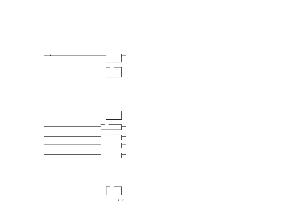
This example program is for a PROFIBUS demonstration using a SLC 5&05 processor with an SST Profibus scanner
(SST-PFB-SLC) in the first slot of the rack. The program is written for 3 drives with one Profibus adapter on the network
(MultiDrive Mode):
Station 0 MD65 with MDCOMM-PBUS
Station 1 MD65
Station 2 MD65
The expample program demonstrates using Logic Command / Reference, Logic Status / Feedback and Parameter
Access using the Parameter Protocol.
On power-up, zero out the transmitt buffer to the Scanner.
0
S:1
15
First Pass
FLL
Fill File
Source
0
Dest
#N20:0
Length
10
FLL
1
MOV
Move
Source
S:3
2561<
Dest
M0:1.4011
?<
MOV
The Scanner is configured to 20 bytes (10 words) of inputs: 4 Bytes "Ctrl/Stat & Ref Fdbk" for each drive (= 12 Bytes)
8 Bytes "Parameter Access"
Read the drives data from the Profibus scanner.
File N10: contains the acutal read data that can be used elsewhere in the ladder program.
Address
Description
M1:1.0 (N10:0) Logic Status Drive 0
M1:1.1 (N10:1) Speed Feedback Drive 0
M1:1.2 (N10:2) Logic Status Drive 1
M1:1.3 (N10:3) Speed Feedback Drive 1
M1:1.4 (N10:4) Logic Status Drive 2
M1:1.5 (N10:5) Speed Feedback Drive 2
M1:1.6 (N10:6) Parameter Access Word 1 (PCA)
M1:1.7 (N10:7) Parameter Access Word 2 (IND)
M1:1.8 (N10:8) Parameter Access Word 3 (PVA 1)
M1:1.9 (N10:9) Parameter Access Word 4 (PVA 2)
2
COP
Copy File
Source
#M1:1.0
Dest
#N10:0
Length
10
COP
Execute LAD 3 - Station 0 Drive Logic
3
JSR
Jump To Subroutine
SBR File Number
U:3
JSR
Execute LAD 4 - Station 1 Drive Logic
4
JSR
Jump To Subroutine
SBR File Number
U:4
JSR
Automatically have the SST-PFB-SCL scanner's watchdog period track that of the
SCL processor (recommended per SST user manual)
Execute LAD 5 - Station 2 Drive Logic
5
JSR
Jump To Subroutine
SBR File Number
U:5
JSR
Execute LAD 6 - Parameter Protocol
6
JSR
Jump To Subroutine
SBR File Number
U:6
JSR
Write the drives' data to the profibus scanner.
File N20: contains the actual write data generated elsewhere in the ladder program.
Station File No. Description
M0:1.0 (N20:0) Logic Command Drive 0
M0:1.1 (N20:1) Speed Reference Drive 0
M0:1.2 (N20:2) Logic Command Drive 1
M0:1.3 (N20:3) Speed Reference Drive 1
M0:1.4 (N20:4) Logic Command Drive 2
M0:1.5 (N20:5) Speed Reference Drive 2
M0:1.6 (N20:6) Parameter Access Word 1 (PCA)
M0:1.7 (N20:7) Parameter Access Word 2 (IND)
M0:1.8 (N20:8) Parameter Access Word 3 (PVA 1)
M0:1.9 (N20:9) Parameter Access Word 4 (PVA 2)
7
COP
Copy File
Source
#N20:0
Dest
#M0:1.0
Length
10
COP
8
END