Rockwell Automation GV3000 AC Pwr Module Ver. 5.0 Hardware Ref, Installation, and Troubleshooting User Manual
Page 80
9Ć6
9.4 Checking Out the Power Modules with Input Power Off
Use the following procedure to check the drive's Power Module circuitry with power off:
DANGER
DĆC BUS CAPACITORS RETAIN HAZARDOUS VOLTAGES AFTER INPUT POWER HAS BEEN
DISCONNECTED. AFTER DISCONNECTING INPUT POWER, WAIT FIVE (5) MINUTES FOR THE DĆC
BUS CAPACITORS TO DISCHARGE AND THEN CHECK THE VOLTAGE WITH A VOLTMETER TO
ENSURE THE DĆC BUS CAPACITORS ARE DISCHARGED BEFORE TOUCHING ANY INTERNAL
COMPONENTS. FAILURE TO OBSERVE THIS PRECAUTION COULD RESULT IN SEVERE BODILY
INJURY OR LOSS OF LIFE.
Step 1. Turn off and lock out input power. Wait five minutes.
Step 2. Remove the drive's cover.
Step 3. Verify that there is no voltage at the drive's input power terminals.
Step 4. Check the DĆC bus potential with a voltmeter as described in section 9.3 to ensure that the
DĆC bus capacitors are discharged.
Step 5. Disconnect the motor from the drive.
Step 6. Check all AĆC line and DĆC bus fuses.
Step 7. If a fuse is blown, use a multimeter to check the input diodes and output IGBTs. See table
9.1.
Note that 1Ć10HP drives do not have replaceable transistor modules: the entire drive must
be replaced if a transistor malfunctions. Intelligent Power Modules (IPM) may be replaced if
they fail in a 60Ć150HP drive.
Step 8. ReĆconnect the motor to the drive.
Step 9. ReĆattach the drive's cover.
Step 10. ReĆapply input power.
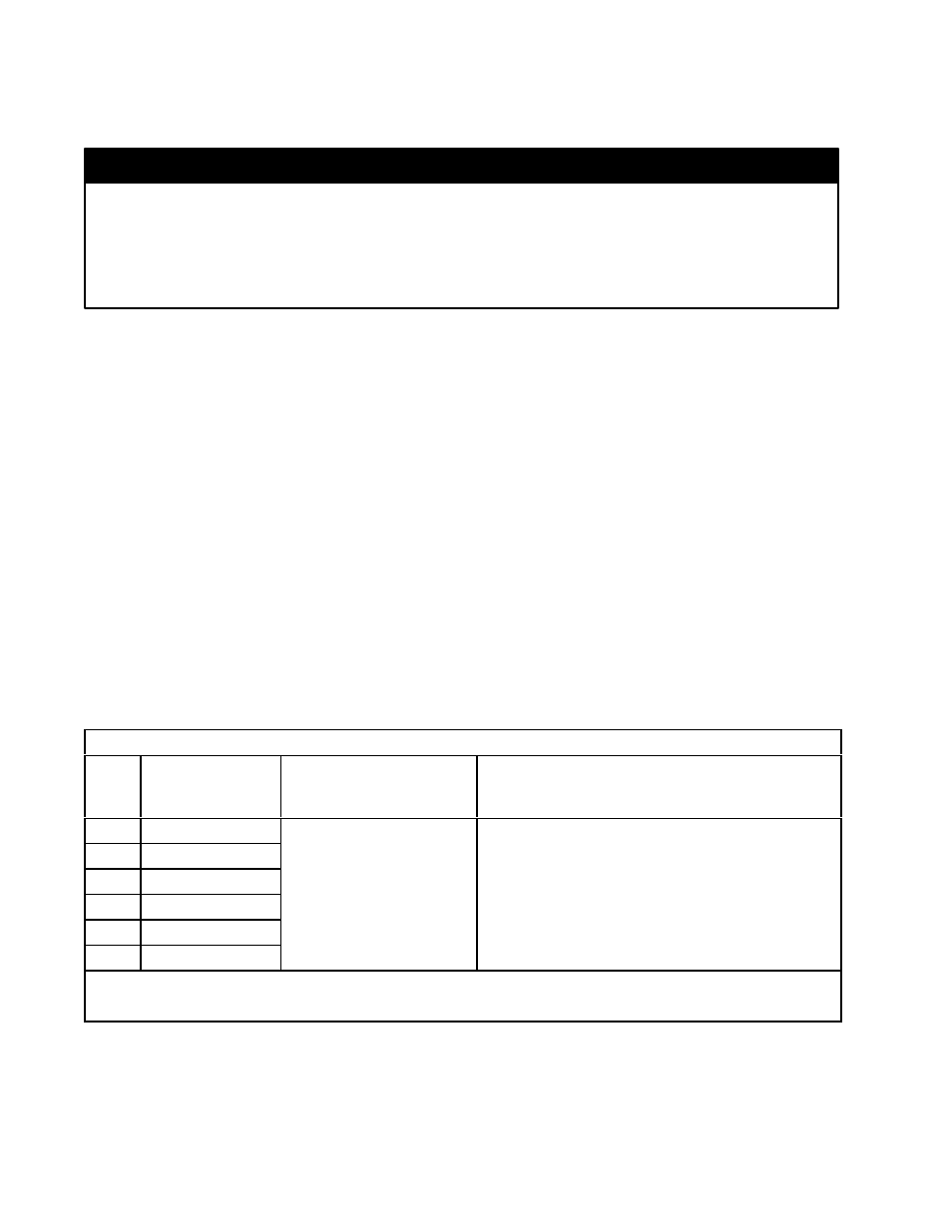
Table 9.1 Ć Resistance Checks
1Ć60HP Drives
Input
Diode
No.
Meter
Connection
(+)
(-)
Component is OK if
resistance (R) is:
Component is defective if:
1
ă*
R/L1
50 < R < 10 Megohm
Continuity (short circuit) or open when the meter is
connected with reversed polarity
2
ă*
S/L2
connected with reversed polarity
3
ă*
T/L3
4
R/L1
**
5
S/L2
**
6
T/L3
**
* (+) DĆC Bus Volts power terminal
** (-) DĆC Bus Volts power terminal