3 rsć232 communication port, 4 option board connector, 5 operator interface module connector – Rockwell Automation GV3000 AC Pwr Module Ver. 5.0 Hardware Ref, Installation, and Troubleshooting User Manual
Page 31: 6 keypad/display
2Ć15
2.7.3 RSĆ232 Communication Port
The Regulator board contains a 9Ćpin DĆshell RSĆ232 communication port (J8). This port provides
RSĆ232 communication between the GV3000 drive and a personal computer running the Control and
Configuration (CS3000) software. See figures 2.8 and 2.9. Refer to instruction manual D2Ć3348, for
more information.
2.7.4 Option Board Connector
The flatĆribbon cable connector (J3) on the left side of the Regulator board is a parallel bus
connection port that provides a means of attaching optional boards such as the DeviceNet board, the
RMI board, or the AutoMax Network Communication board to the GV3000 drive. See figures 2.8
and 2.9. The option board is mounted below the Regulator board inside the drive. Refer to the
appropriate board instruction manual for more information. Refer to section 2.7 of this manual for
more information on optional drive kits.
2.7.5 Operator Interface Module Connector
FlatĆribbon connector J7 provides a means of attaching the optional Operator Interface module
(OIM). The OIM is available for use as a remote keypad for the GV3000.
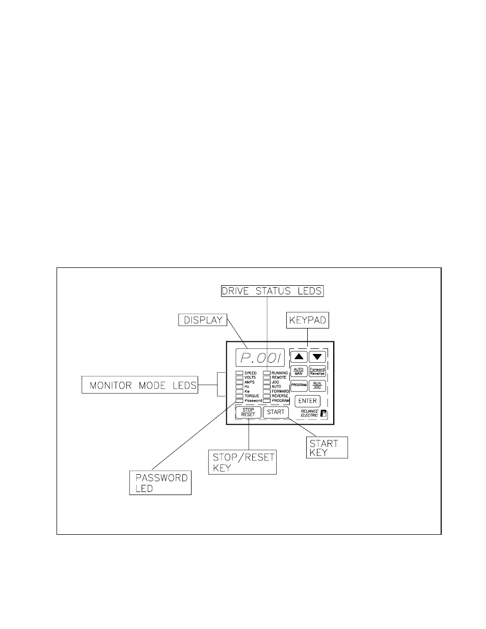
2.7.6 Keypad/Display
The front panel keypad/display is used to program and operate the GV3000 drive. See figure 2.13.
Refer to instruction manual D2Ć3339 for more information.
1. When this LED is on, parameters cannot be modified
from the keypad without entering the correct password
into P.051 (Programming Disable).
1. Stops the drive.
2. Resets faults.
1. Applies power to the motor if the
keypad is selected as the control source.
Figure 2.13 Ć Keypad/Display