Maximum data overlap – Rockwell Automation FactoryTalk Historian SE 3.0 UniInt Interface User Guide User Manual
Page 103
UniInt Interface User Manual
97
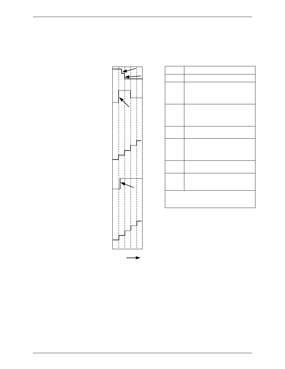
Refer to Figure 7,below which describes the failover action when both interface copies start
at the same time and the latency for an update to the data source is equal to one half of an
update interval.
A
Point Values
1
2
3
4
Time
1 Second
Intervals
C
B
D
15
14
13
12
11
...
4
3
2
1
0
0
1
2
IF1
State
Primary
Backup
Off
Primary
Backup
Off
0
15
14
13
12
11
...
4
3
2
1
0
IF1
Heartbeat
IF2
State
IF2
Heartbeat
Active_ID
Time
Action
T+0
Neither interface is running
T+1
Event A: IF1 starts and notices the
active ID point is 0 so it transitions
to active and writes a 1 to the
active ID point.
T+1.25
Event B: IF2 starts and notices the
active ID point is 0 so it transitions
to active and writes a 2 to the
active ID.
T+1.5
Event C: the update from IF1
reaches the data source
T+2
Event D: IF1 reads a 1 for the
active ID point. Immediately after
this, the update from IF2 reaches
the data source.
T+2.5
IF2 reads a 2 for the active ID point
and remains in the active mode.
T+3
IF1 reads a 2 for the active ID and
immediately transitions to the
backup role.
The last interface to update the active ID
point is the interface that will remain in the
primary role.
Figure 7: Timing chart for both interfaces starting at the same time.
Maximum Data Overlap
Figure 8 shows the timing chart for a scenario that allows the maximum overlapping of data
during a failover.
Error! Objects cannot be created from
editing field codes.