Mount the motor coil, Motor power and feedback cable signal names, Motor power cable signals – Rockwell Automation LZ Series Linear Motors User Manual
Page 15
Publication LZ-UM001A-EN-P - January 2008
Installation 15
Mount the Motor Coil
Follow these procedures to mount the motor coil to your machine slide.
1. Be sure the motor coil mounting face is clean and free of burrs.
2. Position the slide at the end of travel where the cable is to exit.
3. Using M4 x 0.7 bolts with a length as defined by previously in Motor Coil
Mounting Hardware Requirements. Lightly tighten bolts.
4. Using plastic shim stock measure the gap between the motor and
magnet. The gap should be 0.83
±
0.4 (0.033
±
0.15).
5. Torque all bolts to values listed on the tables in Appendix B. When
considering torque values for mounting hardware, take into account the
magnet channel mounting surface material and mounting hardware.
Secure assemblies in place using all mounting holes.
Motor Power and Feedback
Cable Signal Names
The following tables show the motor power and feedback cable signal names.
These cables are not suitable for continuous flexing operation and should be
terminated and connected to flex type cables for any continuous flex
operation.
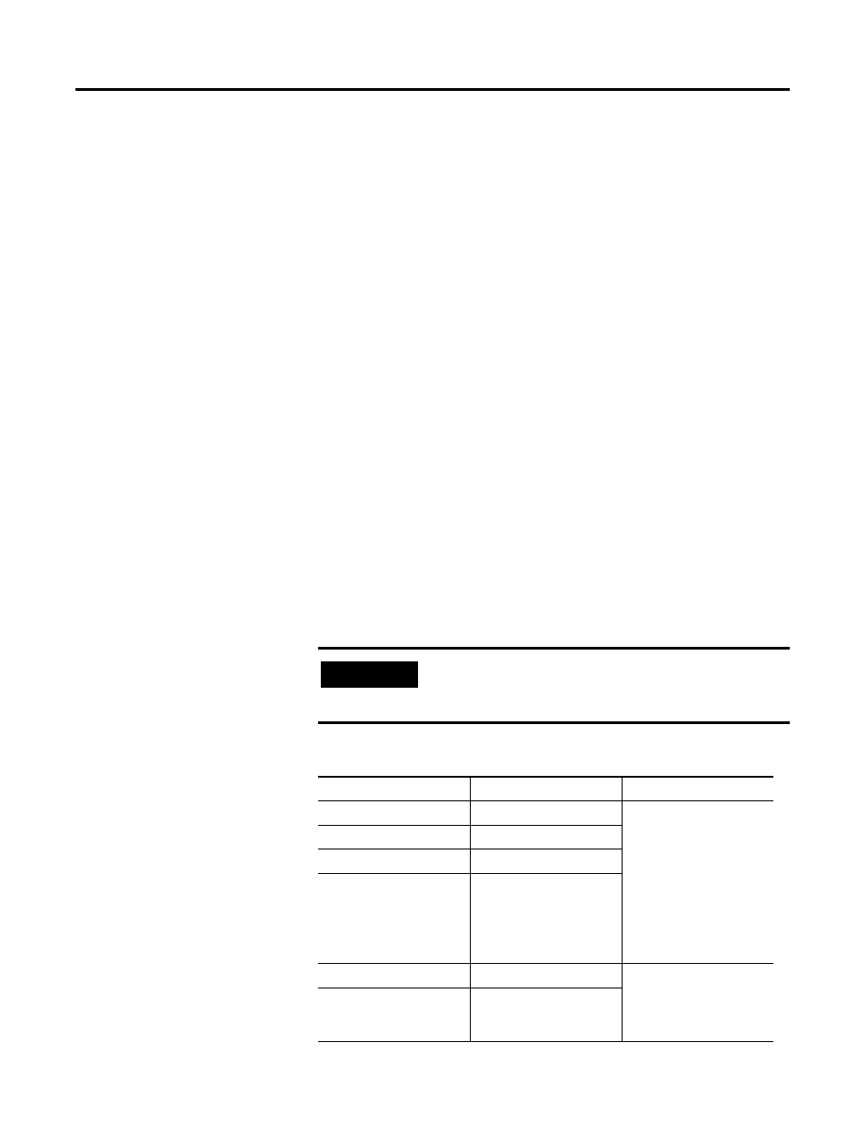
Motor Power Cable Signals
IMPORTANT
Improper wiring can lead to the motor not responding to
commutation commands, run away conditions, or the motor
performing at about half its specified force.
Color from Motor
Designation
Comments
Red
Motor Phase U (A)
• Observe maximum
applied voltage
specification.
• Consult drive manual or
supplier for specific
wiring instructions to
the drive. Wiring is
phase-commutation
sensitive.
White
Motor Phase V (B)
Black
Motor Phase W (C)
Green/Yellow
Motor Ground
•Terminate per drive
manual instructions.
•Shield is not connected
to the motor frame.
Shield Cable
Shield