Precharge control relay cr led indicator, Precharge control relay cr led indicator -3 – Rockwell Automation 20D DC SCR Precharge Module User Manual
Page 25
Start-Up / Troubleshooting
2-3
Applying AC Power to the Drive with the DC SCR Precharge Module
❏ 10.Apply AC power and control voltage (115 VAC) to the DC SCR
Precharge Module. The green LED on the Precharge Control Relay CR
should be on if the drive control logic completes precharge and the SCR
control starts gating the SCR power module.
❏ 11.If the green LED on the Precharge Relay CR is not on at this point,
disconnect incoming power and refer to
for troubleshooting.
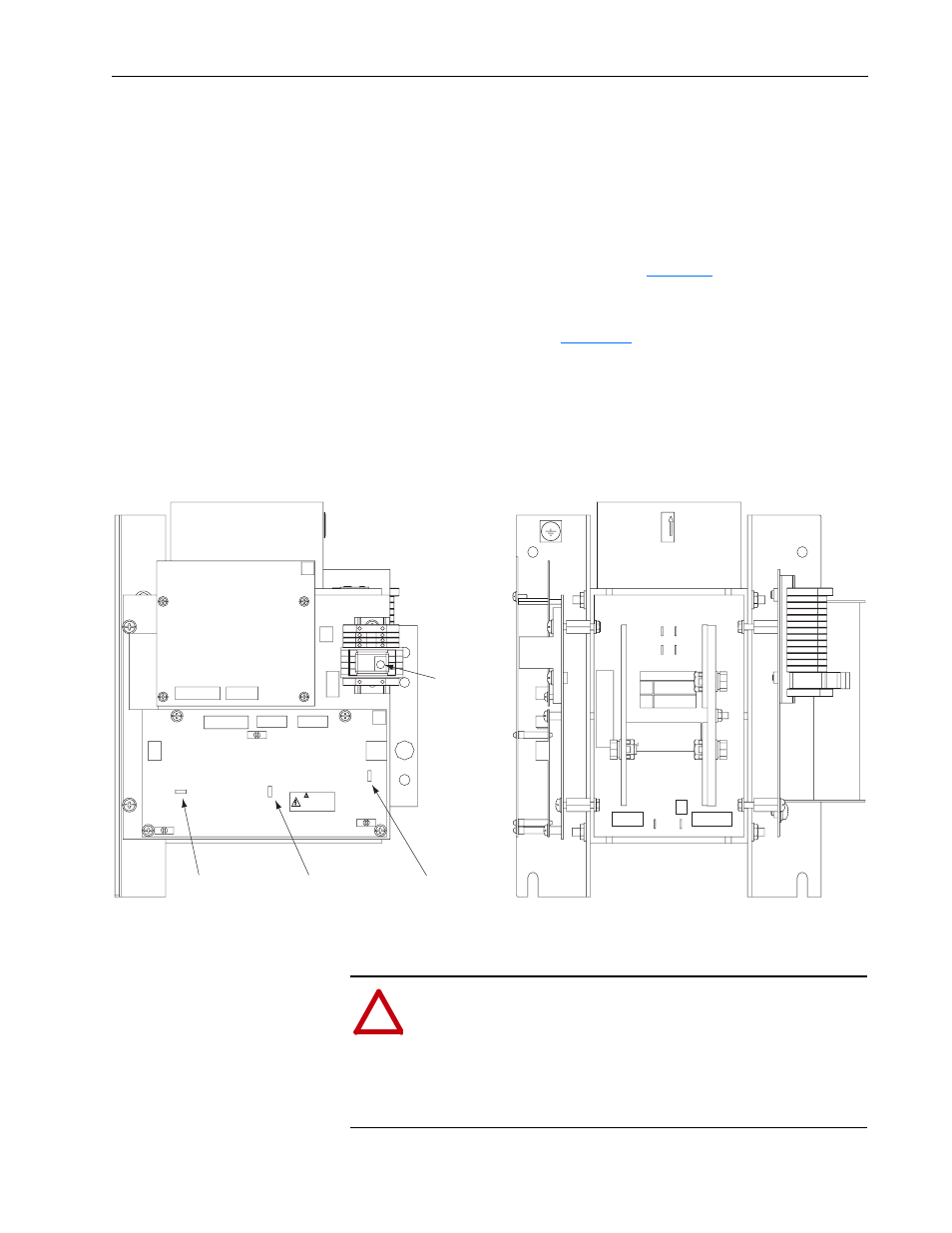
Precharge Control Relay CR
LED Indicator
The DC SCR Precharge LED (
) on the Precharge Control Relay
CR is visible from the board’s side of the Module, depending on the
position of the Module. The Precharge Control Relay CR is mounted on the
terminal block TB1. When the LED is lit solid green, it indicates that the
DC SCR Precharge Module is gating properly and the precharge sequence
is complete.
Figure 2.1 Location of LED on the Precharge Control Relay CR and W* Jumpers
CR
TB1
W1
W3
J3
J3
J1
J1
J2
TB2
W2
AK
K
A
HK
AIR FLOW
A1
A2
CR
TB1A
G
T
NAMEPLATE
+DC IN
+DC OUT
DANGER
CAN CAUSE SHOCK
BURNS, OR DEATH
SURFACES
MAY BE HOT
LED
DANGER
REMOTE SOURCES
DANGER
REMOTE SOURCES
DANGER
RISK OF SHOCK
REPLACE AFTER
SERVICING
(W1) JMP1
TOP VIEW
LEFT SIDE VIEW
(W2) JMP2
(W3) JMP3
GND
!
ATTENTION: The DC SCR Precharge Module is only
operational when the unit is energized. Servicing energized
equipment can be hazardous. Severe injury or death can result
from electrical shock, burn, or unintended actuation of the
controlled equipment. Follow safety-related practices of NFPA
70E, ELECTRICAL SAFETY FOR EMPLOYEE
WORKPLACES. DO NOT work alone on energized equipment!