Typical power and control wiring examples, Typical power and control wiring examples -10 – Rockwell Automation 20D DC SCR Precharge Module User Manual
Page 20
1-10
Installation/Wiring
Typical Power and Control
Wiring Examples
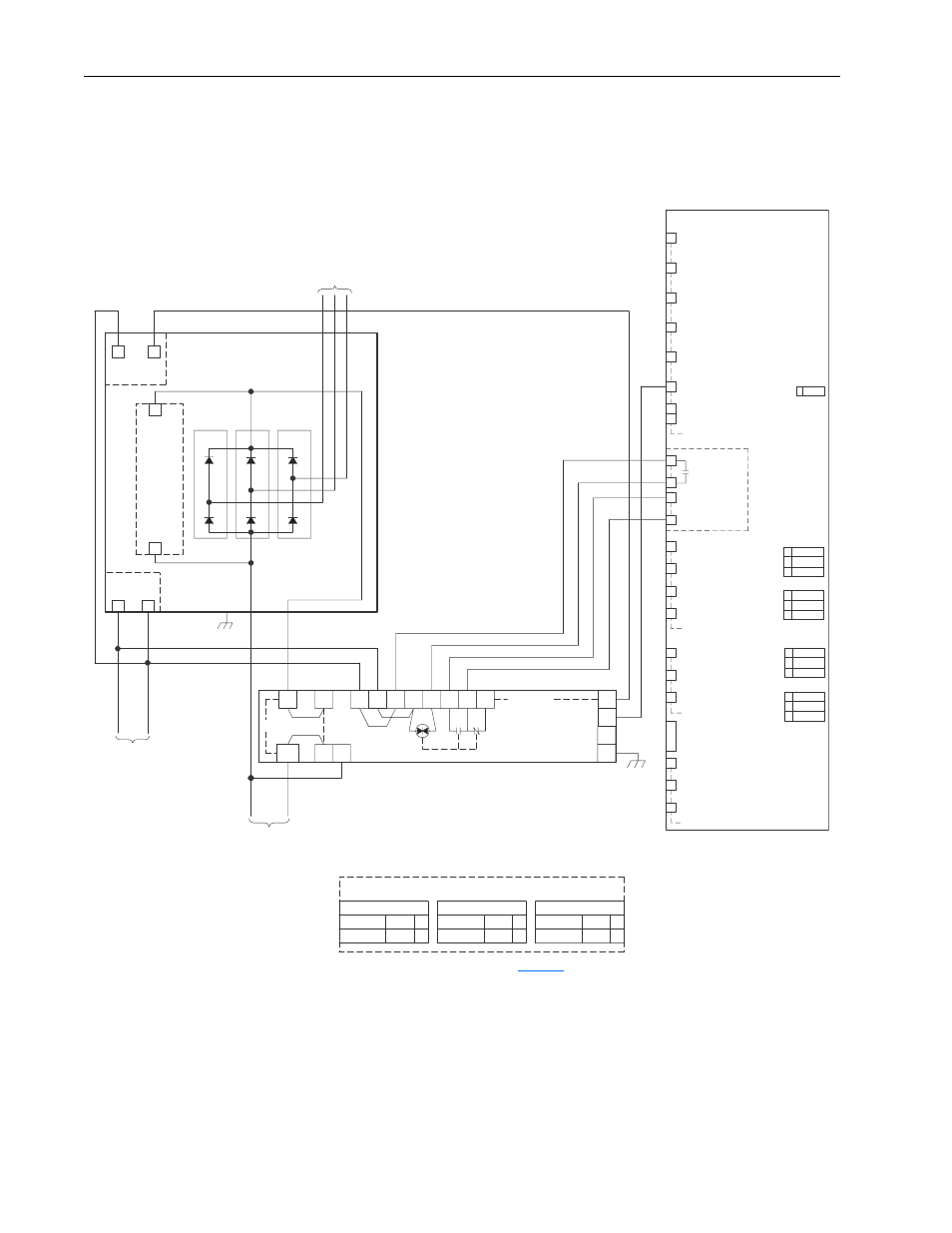
Figure 1.8 Typical Power and Control Wiring of DC SCR Precharge Module for
PowerFlex 700H/700S Drive Applications
J5
Hardware
Enable
IN
11
13
14
12
X50: Precharge
Terminal Strip
15
16
18
17
1
5
6
2
3
1
Enable
2
Digital IN Common
Digital IN Terminal Strip
Digital IN Common
Analog IN 2 (-)
Analog IN 1 (-)
Analog IN 1 (+)
I/O Terminal Block
Precharge
Main Control Board
9
8
10
Shield Bus
5
7
6 Pot Common
Analog OUT Terminal Strip
-10V Pot Reference
+10V Pot Reference
Analog OUT 2 (+)
Analog OUT 1 (+)
Analog OUT Common
Pot Terminal Strip
Analog IN Terminal Strip
Analog IN 2 (+)
4
J4
0-20 mA
0-10V
J3
0-10V
0-20 mA
J2
0-20 mA
0-10V
0-20 mA
± 10V
± 10V
± 10V
± 10V
0-10V
J1
TB1A
DC+
TB2A
Thermostats
Precharge Module
-DC
+DCout
+DCin
EA10
+
-
2
1
2
1
3
1
1
2
3
OUT
IN
2
6
7
5
4
CR
CR
EA11
11
CR
8
12
10
9
EA1
NORMAL
BYPASS
2-3
1-2
(W3) JMP3
X
X
(W2) JMP2
1-2
2-3
BYPASS
INTLK
24 VDC
120 VAC
2-3
1-2
(W1) JMP1
X
D3
D1
D2
1
K
A
AK
K
A
AK
1
1
K
A
AK
To
Drive
A2 Precharge Board Jumper Settings
480 VAC
3-Phase
Input Power
120 VAC
From
Control Power
Bridge
Thermostats
Snubber
Board(s)
6-Pulse Diode Bridge
Bridge
Fans
Neutral
Phase
Digital IN3
Digital IN5 (Aux Fault)
(Parameter 365 = 3)
Digital IN4 (Speed Sel. 1)
(Parameter 364 = 15)
Digital IN2 (Start)
(Parameter 362 = 5)
Digital IN1 (Stop)
(Parameter 361 = 4)
Digital IN6 (Enable)
(Parameter 366 = 1)
X
X
X
X
PowerFlex 700H/700S Control
➊
➊
Remove jumpers when 24 VDC input power is wired
to TB2A-1 and TB2A-2 for interlocking with system
power. Then 120 VAC power must be connected to
TB2A-3 and TB2A-4.
For jumper locations, see
.