Pci riser board options – Rockwell Automation 6181F_P Series E Integrated Display Computers User Manual User Manual
Page 48
48
Rockwell Automation Publication 6181P-UM002D-EN-P - February 2014
Chapter 4
Component Replacement
PCI Riser Board Options
You can use the PCI expansion slot kit, catalog number 6189V-EXTPCIS, to
change the default one-slot PCI riser board to the following:
• Two-slot PCI riser board
• One-slot PCI Express riser board
• Two-slot riser board with one PCI slot and one PCI Express x1 slot
Follow these steps to install the PCI expansion slot kit (the performance
computer is shown).
1. Follow the steps for
2. Remove the computer cover as detailed in
.
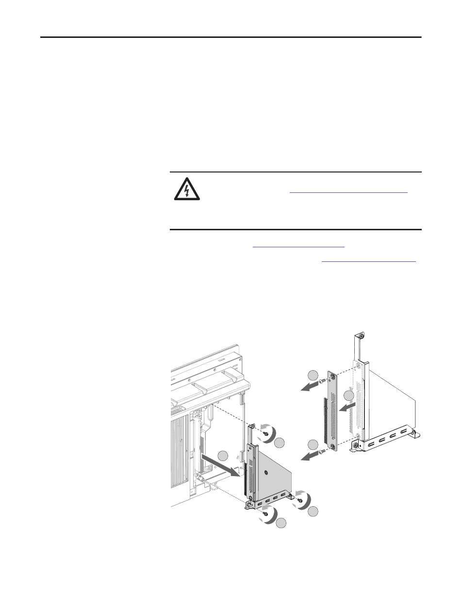
3. Loosen the three screws that secure the PCI riser board bracket (A).
4. Remove the PCI riser board assembly from the chassis (B).
5. Remove the two screws that secure the default riser board (C).
6. Remove the riser board from its bracket (D).
7. Place the default riser board with its screw on a static-dissipating work
surface or inside an antistatic bag.
SHOCK HAZARD: Electrostatic discharge (ESD) can damage the computer and
components. Read and follow
Electrostatic Discharge Precautions on page 36
before removing the rear cover.
Failure to follow proper safety precautions can result in severe electrical shock or
damage to the computer.
D
C
C
A
A
A
B