Connecting two power supplies – Rockwell Automation 2500 CENTERLINE Motor Control Centers Installation Manual User Manual
Page 87
Rockwell Automation Publication 2500-IN001C-EN-P - April 2014
87
IntelliCENTER Options
Chapter 9
Connecting Power Supplies–Remote or in the MCC Line-Up
Connect power supplies according to these guidelines to minimize voltage drops
in the DeviceNet system and ensure proper supply voltage to system devices.
Refer to the Media Design Installation Gu
detailed
connecting instructions.
Network Power Supply and the Protective Earth Circuit
The DeviceNet cable must be connected to the PE circuit at only one location.
The ideal choice is at the power supply. Connect the power supply and 24V DC
common (black wire) to the PE circuit by using #8 AWG wire.
Best PE Practice
•
If the power supply comes installed in the MCC, the black 24V DC
common terminal is connected to the PE within the unit.
•
To improve the connection, use #8 AWG green wire and ground the black
24V DC common terminal to a very stable PE external to the MCC or to
an optional true earth (TE) connection inside the MCC.
•
If the power supply is external, the same recommendations apply.
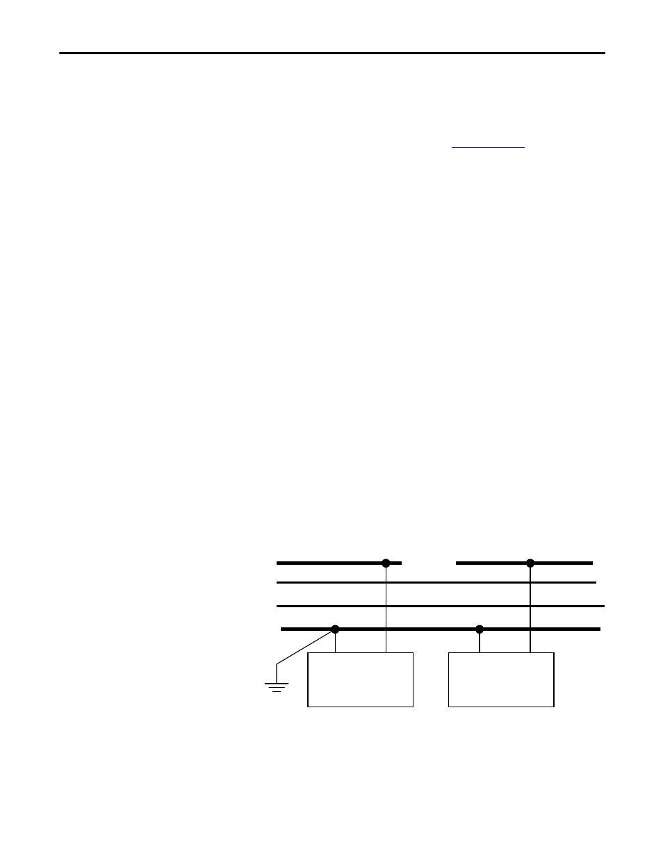
Connecting Two Power Supplies
An additional 24V DC Class 1 power supply must be installed for MCC line-ups
with more than 14 columns. When using two supplies, the red conductor
between the power supplies must be broken. Locate a linking connector between
columns and disconnect the red conductor.
Connect only ONE of the two power supplies to the PE.
Power Supply
Power Supply
Red V+
White CAN_H
Blue CAN_L
Black V- (common)
BREAK