Securing a motor control center, Securing methods – Rockwell Automation 2500 CENTERLINE Motor Control Centers Installation Manual User Manual
Page 29
Rockwell Automation Publication 2500-IN001C-EN-P - April 2014
29
Install Columns
Chapter 3
Securing a Motor Control
Center
Documentation packages shipped with assembled MCCs include an MCC
elevation drawing showing an MCC floor plan layout. To secure a column to the
foundation, refer to the provided floor plan layout and the following procedures.
Refer to
for cable and conduit routing instructions.
Securing Methods
MCC columns or shipping blocks can be bolted or welded to a foundation. Two
mounting channels on the bottom of each MCC column are used for either
securing method.
Weld Down Method
for welding a MCC column or shipping block to a
foundation.
Bolt Down Method
The two mounting channels allow up to four steel M12 bolts (minimum
Property Class 8.8) for each MCC column. We recommend that these bolts be
pre-located and embedded in the foundation before installing each MCC
column. See
through
for mounting bolt locations.
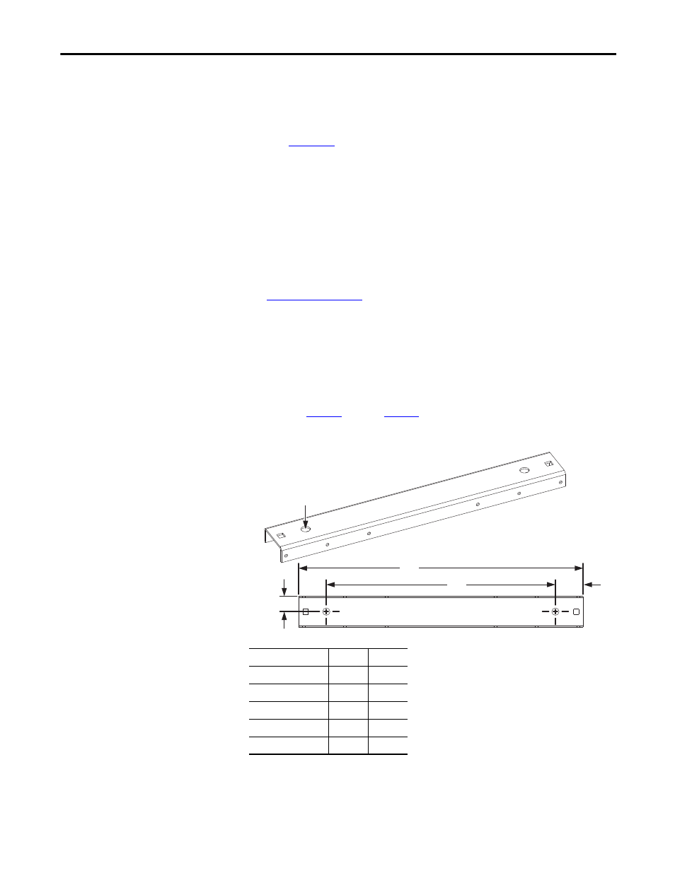
Figure 11 - Mounting Channel Dimensions and Bolt Locations
All dimensions are mm.
MCC Column Width
A
B
600
597
461
700
697
561
800
797
661
900
897
761
1000
997
861
TIP
Mounting channel is not flush with the sides of the MCC column.
A
B
38
68
Mounting holes (2)
18 mm dia.