Rockwell Automation 2500 CENTERLINE Motor Control Centers Installation Manual User Manual
Page 32
32
Rockwell Automation Publication 2500-IN001C-EN-P - April 2014
Chapter 3
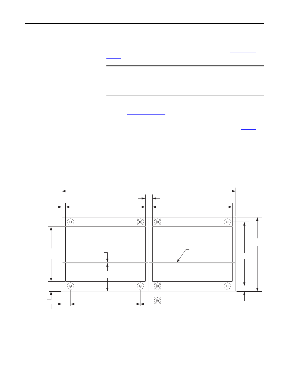
Install Columns
Securing Single-front, Two-column-wide Shipping Blocks
The following instructions are for bolting down the MCC. See
for weld down requirements.
1.
Remove the bottom wireway cover to locate the front mounting channel.
See
for cover location.
2.
Secure the front of the MCC to the foundation with the mounting
dimensions below and the mounting channel requirements on
3.
Replace the bottom wireway cover.
4.
Remove the bottom wireway endplate near the back of the unit to locate
the rear mounting channel. See
for endplate location.
5.
Secure the rear of the MCC to the foundation with the mounting
dimensions below and the mounting channel requirements on
6.
Replace the bottom wireway endplate.
IMPORTANT
Verify there is adequate clearance on the exposed sides of columns to access
the rear mounting bolt locations.
Use steel M12 bolts (minimum Property Class 8.8) to secure columns to the
foundation. Not all bolt locations are used.
1200…2000
542…942
58
6
234
460…860
44
512…712
600…800
438…638
70
81
29
Protective earth
(PE) conductor
FRONT
REAR
542…942
First Column
= Mounting hole location not required.
Dimensions are in mm.
Diagram shows top view
of 600 and 800 mm
column depths.