Rockwell Automation 8720MC 8720MC Regenerative Power Supply User Manual User Manual
Page 63
4-25
Wiring
on the terminal block TB2. Terminal PR3 should be left open.
See Chapter 2, Figure 2.2 "Terminals Blocks on the Main Circuit".
The Precharge/Discharge Time (F.014) may require a larger value
to accommodate the increased precharge time. The Wattage of
Precharge/Discharge Resistor (F.015) should also be increased to
the external precharge resistor wattage.
External circuit case
In the case of the RPS190 if the total capacitance is above
165,000
µ
f but less than 495,000
µ
f an external precharge resistor
connected as shown in Figure 4.10 must be provided. Table 4.8
provides the minimum resistance value for the external precharge
resistor, 1.5 ohms in the case of the RPS190. The wattage [W] is
determined by the equation presented above.
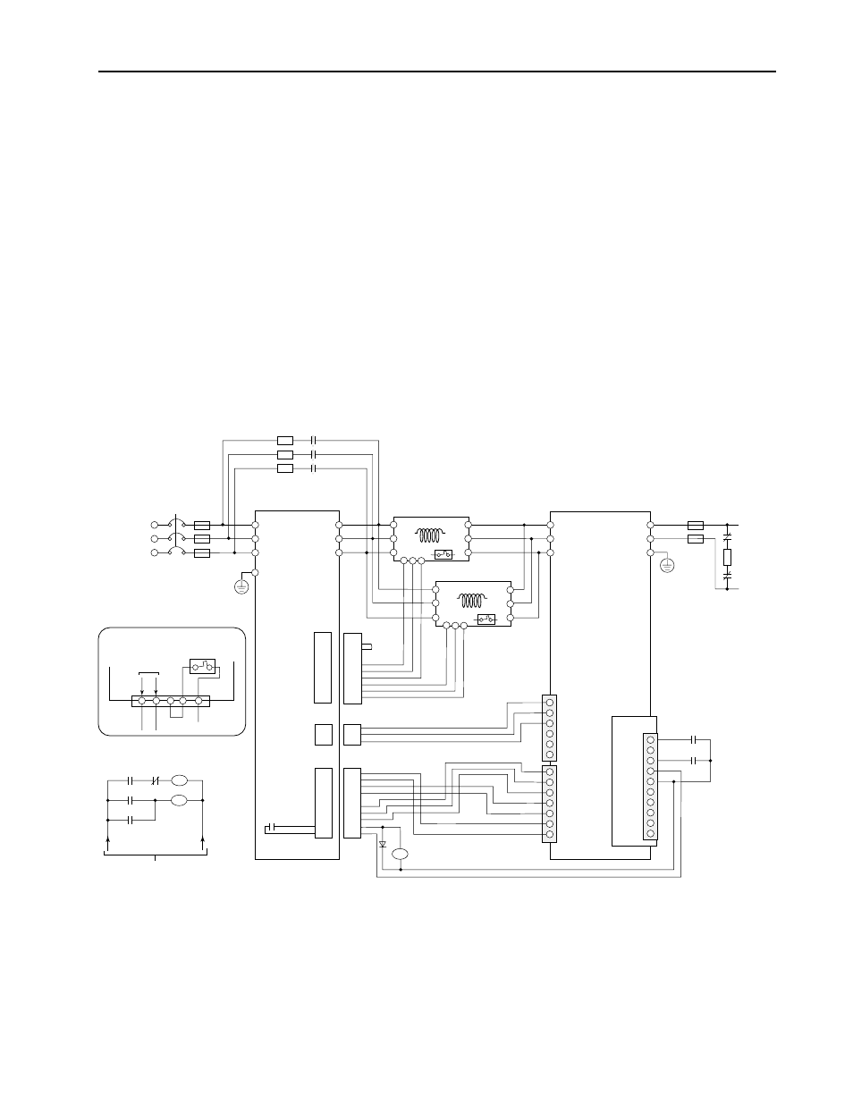
Figure 4.10
Example of Wiring when Precharge/Discharge Circuit of the 8720MC-RPS190 is
configured with an External Circuit
CN2
CN2
CN4
1
2
3
CN4
CN1
MC1
MC2
+24V2
0V2
NC
+24V3
0V3
SENS-out
L1
PR3
PR2
PR1
PRX
MC
PRX
PWR MCX
L4
L5
L6
L2
L3
L1 (R)
L2 (S)
L3 (T)
P
N
G
DISR
DIS
PWR
MCX
Relay for controlling
DC 24V control
DIS
L
1AUX
(R1)
L
2AUX
(S1)
L
3AUX
(T1)
PR1
PR2
PR3
ACL Unit
24V3
0V3
SENS
24V2
0V2
MC1
MC2
MC
RST
PWR
0V
24V
COM
IP
RDY
FR
FR
RED
1 R1
2 S1
3 T1
WHT
BLU
BDSR-1
CN1
G
SS441B:
AC 460V
SS4265:
AC 230V
L4
L5
L6
L1
L2
L3
L4
L5
L6
L1
L2
L3
<1
8720MC-EF190-VB
EMC Filter Unit
8720MC-RPS190
YLW
BLK
RED
R
BL
Y
BR
BR
Circuit
Breaker
(CB)
A1
A2
A3
A4
A5
B1
B2
B3
B4
B5
A1
A2
A3
A4
A5
B1
B2
B3
B4
B5
A1
A2
A3
A4
A5
B1
B2
B3
B4
B5
A1
A2
A3
A4
A5
B1
B2
B3
B4
B5
R1
S1
T1
Fan 3
Fan 2
RED
BLK
YLW
YLW
RED
BLK
Short
Terminals on ACL Unit
Fan
DC Output
Fuse
ACL Unit
AC
Input
Fuse
MCX
PRX
DIS
+24V
MC
MC
Power for Sequence Circuit
DC
Contactor
1> Remove the jumper between PR2 and PR3.
2> Use a relay with contact of which minimum applicable load is 5 mA and below.
3> Refer to the figure at the lower left corner of this figure indicating the terminals on the ACL unit. When the fan
inside the ACL unit is connected with an external power supply, do not fail to connect with the power supply
designated by NEC Class 2 (Power supply limited to 100VA and below and 8A and below even in case of Error).
Avoid the high voltage portion and the high temperature portion of the ACL unit when wiring the fan inside the
ACL unit.
4> Use the ACL unit in maximum surrounding air temperature of 55 degree C (131 degree F) and below.
<4
<3
<3
<2
<4