And l, And to the control power terminals (l – Rockwell Automation 8720MC 8720MC Regenerative Power Supply User Manual User Manual
Page 42
4-4
Wiring
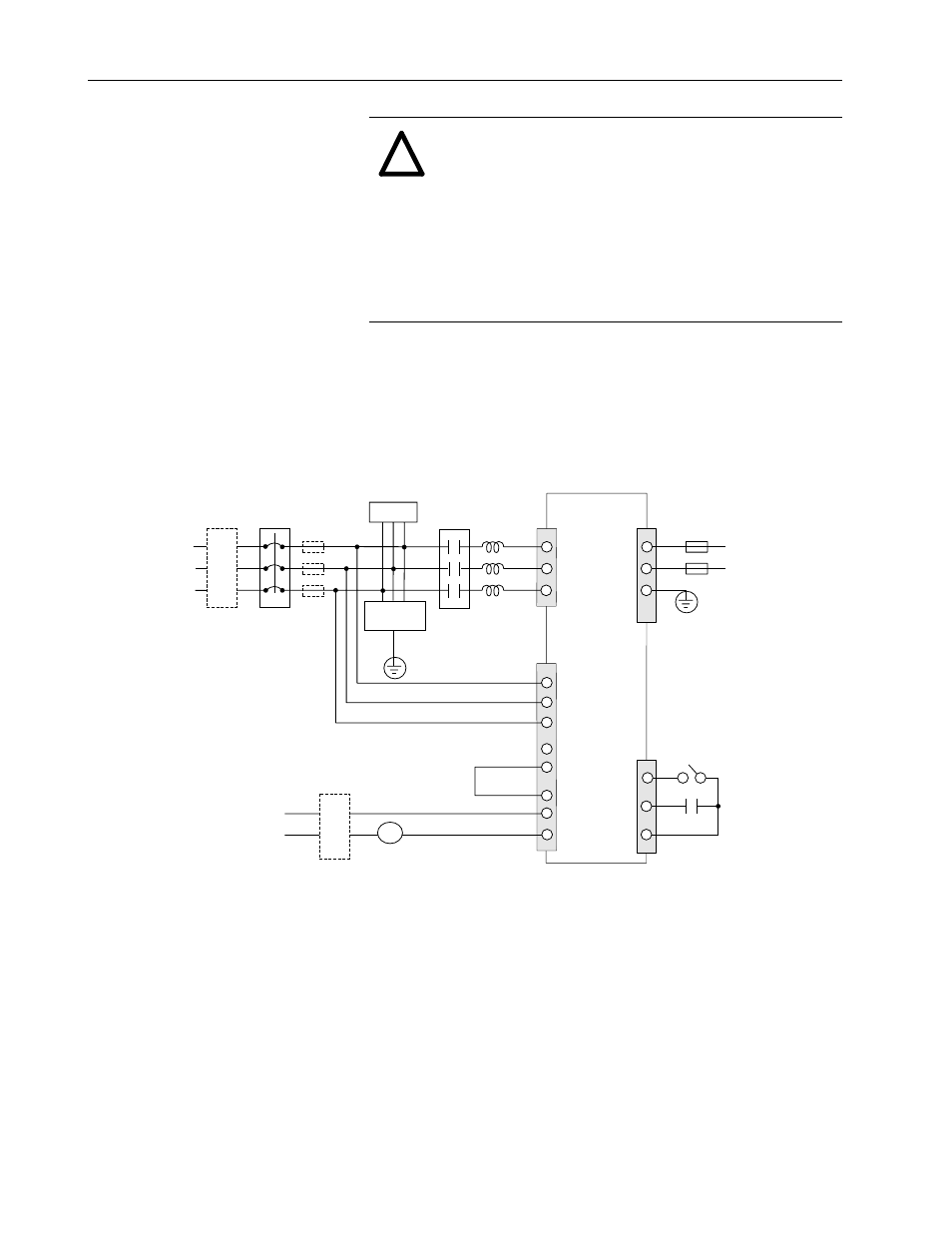
Figure 4.1
Typical Connection of AC Input Power Wiring for Single Unit of
Model 8720MC-RPS027 and 8720MC-RPS065
ATTENTION:
Special caution must be paid to wiring
to the 8720MC-RPS Regenerative Power Supply when
connecting multiple units in parallel. The phases of AC
input power to the main power supply terminals (L
1
, L
2
and L
3
) and to the control power terminals (L
1AUX
,
L
2AUX
, and L
3AUX
) and the polarity of DC bus output (P
and N) of all the connected units must be the same.
Failure to observe this precaution could result in
destruction of the equipment, severe bodily injury or
loss of life.
!
MC
L
1
P
L
1AUX
L
2AUX
L
3AUX
PR1
PR2
PR3
MC1
MC2
PWR
MC
24V
8720MC-RPS
Regenerative
Power Supply
Unit
MC
Circuit
Breaker <4
(CB)
Line Filter <5
for AC Input
Power
Single-phase
Line Filter <5
Main
Magnetic
Contactor
(MC)
Reactor <11
Harmonic
Filter
Terminal Block for
Control Power (TB2)
100 to 115 VAC
or
200 to 230 VAC
380 to
460 VAC
RUN On/Off
Terminal Block for
Sequence Signals (TB3)
Terminal Block for Main
Power Supply (TB1)
Protection Fuse <2
Terminals P and N <6
of Load Equipment
1>
The phases of the AC input power to the main supply terminals L
1
, L
2
and L
3
must be same as those of the control power
to the control power terminals L
1AUX
, L
2AUX
and L
3AUX
.
2>
It is recommended to install the DC bus protection fuses on the both lines to the terminals P and N to prevent ground fault,
when more than one drive is connected to the 8720MC-RPS Regenerative Power Supply.
3> Turn ON the switch SW7-1 on the Regulator Board without fail.
4> Both a three-phase circuit breaker and fuses are not required. Check your local code to determine if fuses should be
used instead of a circuit breaker.
5> When the 8720MC-RPS Regenerative Power Supply must conform with the requirements of CE Mark, install a line filter in
the AC input power line and a single-phase line filter in the power supply line to the main magnetic contactor.
6> The length of the DC bus wiring runs should not exceed 2 meters. It is also recommended to use twisted shielded cable.
7> The length of the wiring in the cabinet must be as short as possible.
8> The length of the wiring from the E terminal of the Harmonic Filter to the Grounding Terminal must be as short as possible.
9>
The physical location of the Harmonic Filter and Varistor relative to the Contactor and Line Reactor is important.
Connect these devices in the relative positions shown in this illustration.
10>
Because driving current of sequence input signals is 5mA and below, use a contact of which minimum applicable load is 5mA and below.
11>
Use the reactor in maximum surrounding air temperature of 55 degree C (131 degree F) and below.
Varistor
Fuse <4
for
Power
Supply
<8, 9
L
3
L
2
G
N
E
<10
<1