Rockwell Automation 8720MC 8720MC Regenerative Power Supply User Manual User Manual
Page 55
4-17
Wiring
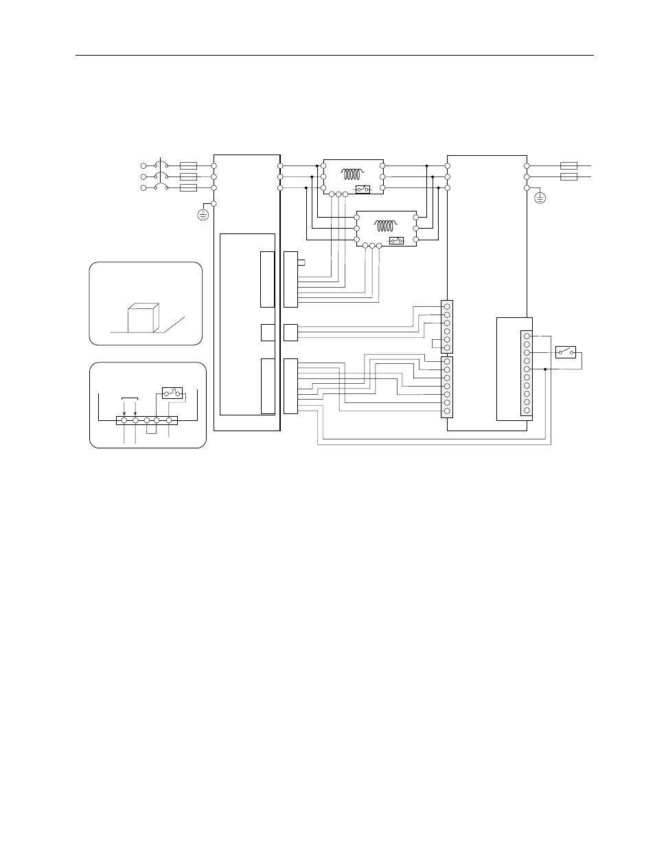
Figure 4.6
Typical Connection of AC Input Power Wiring for Single Unit of
Model 8720MC-RPS190 Unit
CN2
FMI-1
CN2
CN4
1
2
3
CN4
CN1
MC1
MC2
+24V2
0V2
NC
+24V3
0V3
SENS-out
+24V
MC
L1
L4
L5
L6
L2
L3
L1 (R)
L2 (S)
L3 (T)
P
N
G
L
1AUX
(R1)
L
2AUX
(S1)
L
3AUX
(T1)
PR1
PR2
PR3
ACL Unit
ACL Unit
24V3
0V3
SENS
24V2
0V2
MC1
MC2
MC
RST
PWR
0V
24V
COM
IP
RDY
FR
FR
RED
1 R1
2 S1
3 T1
WHT
BLU
BDSR-1
CN1
G
8720MC-RPS190:
380 to 460 VAC
L4
L5
L6
L1
L2
L3
L4
L5
L6
L1
L2
L3
<1, 6
<1, 6
8720MC-EF-190-VB
EMC Filter Unit
8720MC-RPS
Regenerative
Power Supply Unit
Fan
YLW
BLK
BL
BR
BR
RED
R
Y
Short
Terminals on ACL Unit
1> Refer to the figure at the lower left corner of this figure indicating the terminals on the ACL unit. When the fan
inside the ACL unit is connected with an external power supply, do not fail to connect with the power supply
designated by NEC Class 2 (Power supply limited to 100VA and below and 8A and below even in case of Error).
Avoid the high voltage portion and the high temperature portion of the ACL unit when wiring the fan inside the
ACL unit.
2> The phases of the AC input power to the main supply terminals L
1
, L
2
and L
3
must be same as those of the control
power to the control power terminals L
1AUX
, L
2AUX
and L
3AUX
.
3> It is recommended to install the DC bus protection fuses on the both lines to the terminals P and N to prevent ground
fault, when plural number of load equipment is connected to the 8720MC-RPS Regenerative Power Supply.
4> Turn ON the switch SW7-1 on the Regulator Board without fail.
5> Because driving current of sequence input signals is 5mA and below, use a contact of which minimum applicable
load is 5mA and below.
6> Use the ACL unit in maximum surrounding air temperature of 55 degree C (131 degree F) and below.
Fuse
for
Power
Supply
Circuit
Breaker
(CB)
Protection
Fuse
<3
RUN On/Off
A1
A2
A3
A4
A5
B1
B2
B3
B4
B5
A1
A2
A3
A4
A5
B1
B2
B3
B4
B5
A1
A2
A3
A4
A5
B1
B2
B3
B4
B5
A1
A2
A3
A4
A5
B1
B2
B3
B4
B5
R1
S1
T1
Fan 3
Fan 2
RED
BLK
YLW
YLW
RED
BLK
<5
<2
CN1 and CN2 of EMC
Filter Unit
B 12345
A 12345
Pin layout
FMI-1
Board
<1