Rockwell Automation 8720MC 8720MC Regenerative Power Supply User Manual User Manual
Page 43
4-5
Wiring
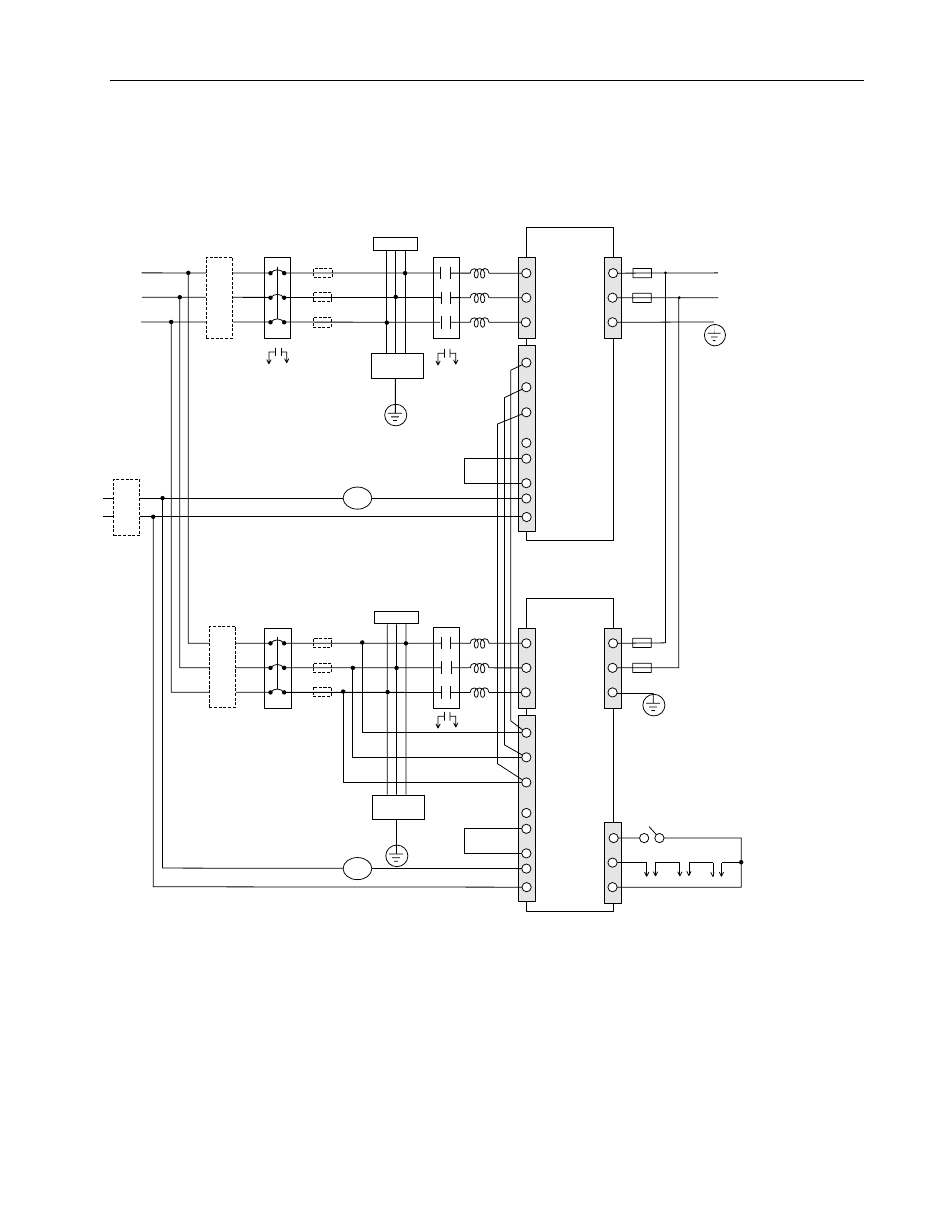
Figure 4.2
Typical Connection of AC Input Power Wiring for Two Paralleled Units of
Model 8720MC-RPS027 and 8720MC-RPS065
L
1
L
2
L
3
P
N
G
L
1AUX
L
2AUX
L
3AUX
PR1
PR2
PR3
MC1
MC2
8720MC-RPS
Regenerative Power
Supply Unit 2
(Slave Unit)
8720MC-RPS
Regenerative Power
Supply Unit 1
(Master Unit)
L
1
L
2
L
3
P
N
G
L
1AUX
L
2AUX
L
3AUX
PR1
PR2
PR3
MC1
MC2
PWR
MC
24V
MC1
CB2
CB2
MC2
RUN On/Off
MC2
MC1
MC2
MC1
Reactor
(L1)
Main
Magnetic
Contactor
(MC1)
Harmonic
Filter
Circuit
Breaker <4
(CB1)
Circuit
Breaker <4
(CB2)
Line Filter <6
for AC
Input
Power
Line Filter <6
for AC
Input
Power
Single-phase
Line Filter <6
Main
Magnetic
Contactor
(MC2) Reactor
(L2)
Harmonic
Filter
Protection
Fuse <2
Protection
Fuse <2
Terminals
P and N
of Load
Equipment
380 to
460 VAC
100 to
115 VAC
or
200 to
230 VAC
1> The phases of the AC input power to the main supply terminals L
1
, L
2
and L
3
must be same as those of the control power to the control power terminals
L
1AUX
, L
2AUX
and L
3AUX
. The phases of the control power L
1AUX
, L
2AUX
and L
3AUX
for the slave unit(s) must also be same as those for the master unit.
2> It is recommended to install the DC bus protection fuses on the both lines to the terminals P and N to prevent ground fault, when more
than one drive is connected to the 8720MC-RPS Regenerative Power Supply.
3> Turn ON the switches SW7-1 and SW7-2 on the Regulator Board without fail.
4> Both a three-phase circuit breaker and fuses are not required. Check your local code to determine if fuses should be used instead of a circuit breaker.
5> The slave circuit breaker must be provided with an auxiliary contact as a safety interlock to the master. Use fuses with a slightly higher current rating
if your local code requires them.
6> When the 8720MC-RPS Regenerative Power Supply must comform with the requirements of CE Mark, install a line filter in the AC input power line and
a single-phase line filter in the power supply line to the main magnetic contactor.
7> The length of the DC bus wiring runs should not exceed 2 meters. It is also recommended to use Bus bar for the common bus sized to 1.75 times the total
continuous current output of the RPS units.
8> The length of the wiring in the cabinet must be as short as possible.
9> The length of the wiring from the E terminal of the Harmonic Filter to the Grounding Terminal must be as short as possible.
10> The physical location of the Harmonic Filter and Varistor relative to the Contactor and Line Reactor is important. Connect these devices in the relative positions
shown in this illustration.
11> Because driving current of sequence input signals is 5mA and below, use a contact of which minimum applicable load is 5mA and below.
12> Use the reactor in maximum surrounding air temperature of 55 degree C (131 degree F) and below.
Varistor
Varistor
Fuse <4
for
Power
Supply
Fuse <4
for
Power
Supply
<9, 10
E
<9, 10
E
<5, 11
<12
<1
<12
<7