Rockwell Automation 61C544A RTD Module User Manual
Page 22
4Ć6
4.1.5
Low Low Alarm Status Register (Register 19)
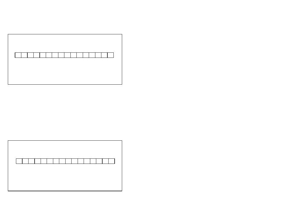
Register 19 indicates the current status of each configured channel's
Low Low alarm. See figure 4.5. A bit is set in this register whenever a
channel's input value is less than the configuredLow Low alarm limit.
The bit is reset when the input value returns to a level above the
configuredlimit.
Register 19
Bits 0Ć15
Bit 0ă=ăChannel 0
Bit 5ă=ăChannel 5
Bit 10ă=ăChannel 10
Bit 1ă=ăChannel 1
Bit 6ă=ăChannel 6
Bit 11ă=ăChannel 11
Bit 2ă=ăChannel 2
Bit 7ă=ăChannel 7
Bit 12ă=ăChannel 12
Bit 3ă=ăChannel 3
Bit 8ă=ăChannel 8
Bit 13ă=ăChannel 13
Bit 4ă=ăChannel 4
Bit 9ă=ăChannel 9
Bit 14ă=ăChannel 14
Bit 15ă=ăChannel 15
R
R
R
R
R
R
R
R
R
R
R
R
R
R
R
R
15 14 13
12 11 10
9
8
7
6
5
4
3
2
1
0
Figure 4.5 Ć Low Low Alarm Status Register
4.1.6
Out of Range Status Register (Register 20)
Register 20 indicates the current status of each configured channel's
Out of Range alarm. See figure 4.6. A bit is set in this register
whenever a channel's A/D input value exceeds the physical
limitations of the A/D converter. These limits are -200
o
C to 500
o
C.
The bits in this register are not latchedautomatically. If you want a bit
to be latchedthe first time a value goes out of range, you must latch
it through the application program.
If an input is identified as being out of range, the most probable
cause is that a wire between the module and the RTD has either not
been connectedor has been broken.
Register 20
Bits 0Ć15
Bit 0ă=ăChannel 0
Bit 5ă=ăChannel 5
Bit 10ă=ăChannel 10
Bit 1ă=ăChannel 1
Bit 6ă=ăChannel 6
Bit 11ă=ăChannel 11
Bit 2ă=ăChannel 2
Bit 7ă=ăChannel 7
Bit 12ă=ăChannel 12
Bit 3ă=ăChannel 3
Bit 8ă=ăChannel 8
Bit 13ă=ăChannel 13
Bit 4ă=ăChannel 4
Bit 9ă=ăChannel 9
Bit 14ă=ăChannel 14
Bit 15ă=ăChannel 15
R
R
R
R
R
R
R
R
R
R
R
R
R
R
R
R
15 14 13
12 11 10 9
8
7
6
5
4
3
2
1
0
Figure 4.6 Ć Out of Range Status Register