Rockwell Automation 61C544A RTD Module User Manual
Page 15
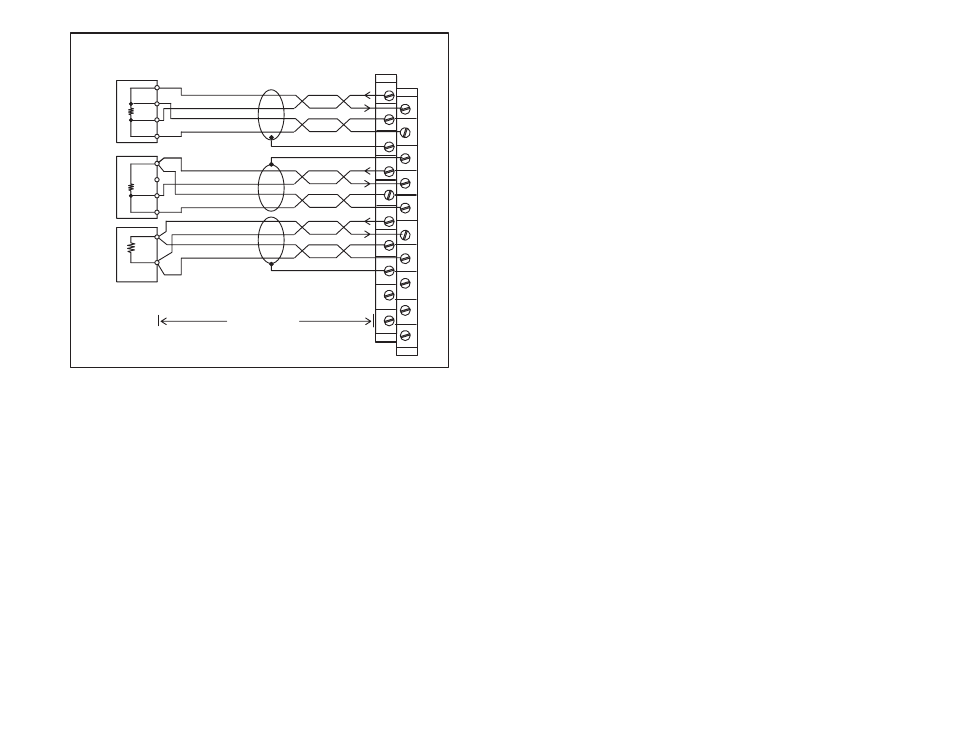
3Ć3
ÉÉ
Red
Black
White
Black
4ĆWire
RTD
3ĆWire
RTD
2ĆWire
RTD
Terminal Board
M/N 61C545 or
Field Wiring
500 Feet Max.
Belden 9502
1
2
4
6
8
10
12
14
16
V+
V-
Shield
Shield
V+
V-
V+
V-
I
O
I
R
I
O
I
R
I
O
I
R
Shield
ЙЙ
ЙЙ
ЙЙ
ЙЙ
ЙЙ
15
18
20
M/N 61C546
Red
Black
White
Black
Red
Black
White
Black
Figure 3.2 Ć RTD Wiring Connections
Step 4.
Take the RTD module out of its shipping container. Take it
out of its antiĆstatic bag. Be careful not to touch the
connectors on the back of the module.
Step 5.
Insert the module into the desired slot in the rack. Use a
screwdriver to secure the module into the slot.
Step 6.
Attach the cables between the terminal board assemblies
and the module. Be sure that the DĆshell connectors are
oriented properly. Use a screwdriver to secure the DĆshell
connectors to the terminal board assemblies and the
module.
Step 7.
Turn on power to the system.
Step 8.
Connect the programming terminal to the system and run
the ReSource Programming Executive Software.
Stop all programs that may be running.
Configure the RTD channels you are using by following
the procedure in section 4.2. You cannot monitor the
registers on the module until you have configured the
channels. When you are done configuring, read the
channels' default values to verify that the installation is
correct. Refer to sections 4.1.1 to 4.1.15 for the default
values.