Rockwell Automation 61C613 16 Channel Analog Input Module User Manual
Page 19
4Ć3
4.2.2
Module Initialization
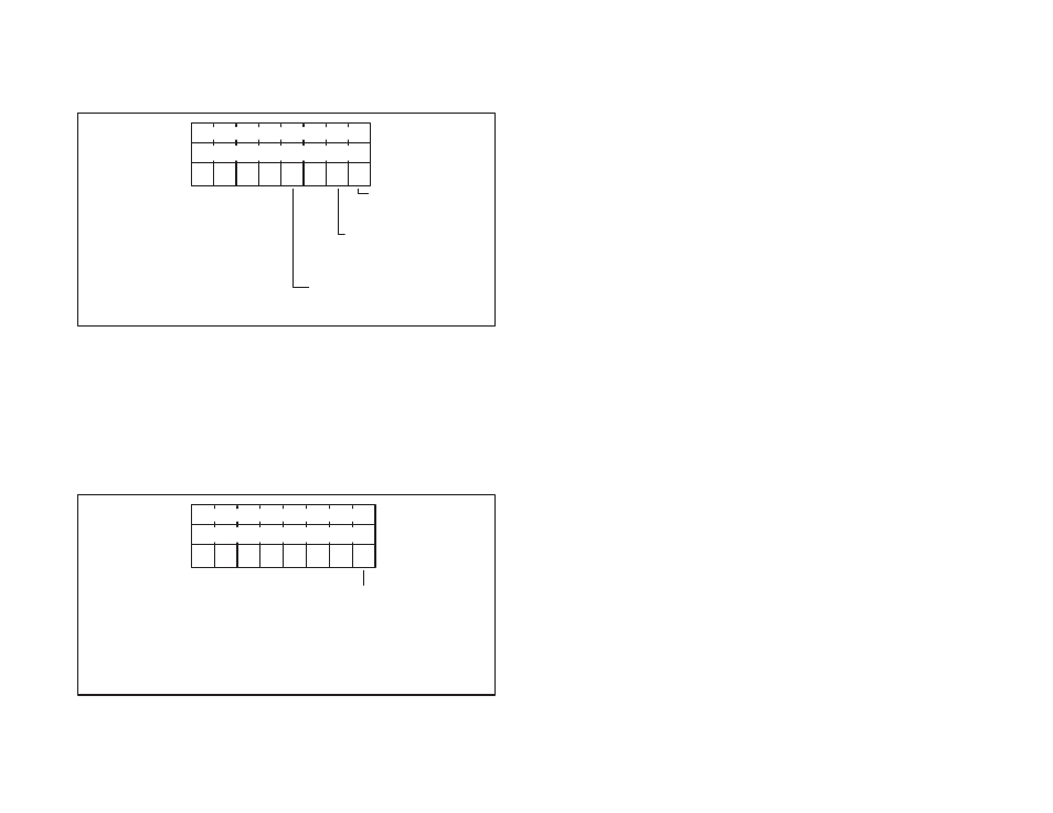
Whenever power is turned on to the rack or the module is reset, it is
necessary to initialize the module. Module initialization must follow
module reset or powerĆup. The initialization command contains the
following information:
Location (M+0)
0
Location (M+1)
0
Location (M+2)
0
0
0
0 rw 0
rw rw
Power line frequency
ą0 Ć 60 Hz
ą1 Ć 50 Hz
Temperature units for therĆ
mocouple readings
ą0 Ć Centigrade
ą1 Ć Fahrenheit
Data acquisition mode
ą0 Ć OnĆcommand
ą1 Ć Continuous
The power line frequency should be selected for maximum rejection
of power lineĆinduced noise.
The data acquisition mode specifies how the analog input channels
will be read, either onĆdemand (refer to section 4.2.10) or
continuously (refer to sections 4.2.7, 4.2.8, and 4.2.9).
4.2.3
Write Channel Number
The write channel number command sets a value into the module's
channel register pointer, which defines the A/D channel for
channelĆspecific commands. The write channel number command
contains the following information:
Location (M+0)
20
Location (M+1)
channel number
Location (M+2)
0
0
0
0
0
0
0
w
Auto increment switch
0 Ć Consecutive channelĆ
specific commands will not afĆ
fect the channel register
1 Ć The channel register will be inĆ
cremented after each channel
specific command
Valid channel numbers range from 0 to 15, corresponding to
channels 0Ć15.