Dcs 5000/automax installation verification – Rockwell Automation 61C613 16 Channel Analog Input Module User Manual
Page 14
3Ć2
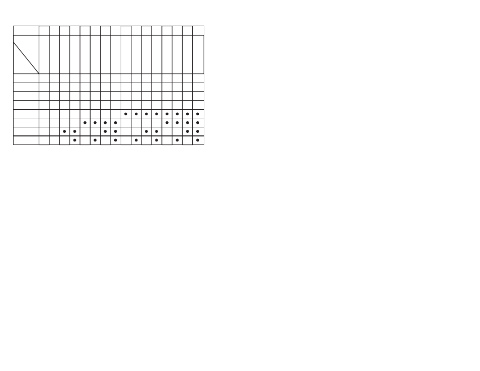
Table 3.2Ć DCS 5000 Slot Configuration
Slot #
0
1
2
3
4
5
6
7
8
9 10 11 12 13 14 15
2
2
2
2
2
2
2
2
2
2
2
2
2
2
base
address
(HEX)
Switch
- -
2
0
0
0
0
3
0
0
0
0
4
0
0
0
0
5
0
0
0
0
6
0
0
0
0
7
0
0
0
0
8
0
0
0
0
9
0
0
0
0
A
0
0
0
0
B
0
0
0
0
C
0
0
0
0
D
0
0
0
0
E
0
0
0
0
F
0
0
0
0
S1Ć1
S1Ć2
S1Ć3
S1Ć4
S1Ć5
S1Ć6
S1Ć7
S1Ć8
- -
- -
- -
- -
- -
- -
- -
- -
ăăăăăăăăăăD
ă=ăSwitch is closed
ăăăăăăăăăă-
ă=ăillegal slot
Step 4.
Insert the module into the desired slot in the rack. Use a
screwdriver to secure the module into the slot.
Step 5.
Attach the 50Ćpin flat cables to their mating halves on the
module. Attach the cables by aligning the triangle marks
on the cable end and the board socket. Make certain that
the connectors are the proper ones for this module. The
cable for channels 0Ć7 attaches to the middle connector.
The cable for channels 8Ć15 attaches to the lower
connector.
Step 6.
Turn on power to the rack.
Step 7.
Verify the installation. For DCS 5000/AutoMax, read the
section entitled DCS 5000/AutoMax Installation
Verification. For AutoMate, go on to the section entitled
AutoMate Installation Verification."
DCS 5000/AutoMax Installation
Verification
Verify the installation by connecting the programming terminal to the
system and running the ReSource Programming software. Note that
you will need the application program disk that came with the
ReSource Programming Software. Use the appropriate size disk for
your particular disk drive. Perform the following steps to verify the
installation of the module:
a. Edit the file SETUP613.BAS in the DCS subdirectory. Customize
the DATA statements beginning at statement 20000 to correctly
describe your configuration.