0 installation, 1 initial installation – Rockwell Automation 61C613 16 Channel Analog Input Module User Manual
Page 13
3Ć1
3.0 INSTALLATION
This section describes how to install and remove the module and its
cable assembly.
3.1
Initial Installation
Use the following procedure to install the module:
Step 1.
Turn off power to the system. All power to the rack as well
as all power to the wiring leading to the rack should be off.
Step 2.
Mount the proper termination panel (61C614 or 61C615).
Refer to the Thermocouple/Voltage Termination Panel
Instruction Manual (JĆ3646Ć1) or the RTD Termination
Panel Instruction Manual (JĆ3645Ć1) for specific
information.
Step 3.
Set the address jumpers on the module for the slot in
which the module will be located. The address jumpers
are located on switch S1. Refer to table 3.1 for the
AutoMate 30/40 and table 3.2 for the DCS 5000/AutoMax.
Note that the slot numbers correspond to actual rack slot
numbers.
If you are using a DCS rack and you are also using a
microĆregulator in that rack, there is an important
restriction on the slots the input module may occupy. The
microĆregulator may be placed only in slots that fall in two
groups: 5 through 8, and 11 through 14. The 61C613 may
not occupy a slot in a group that contains a
microĆregulator.
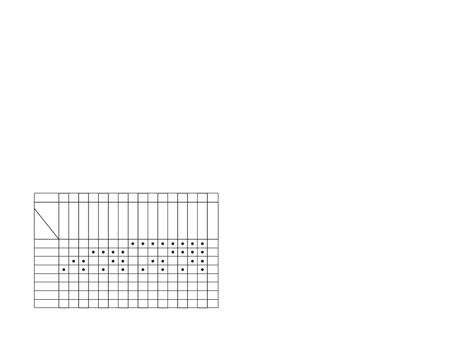
Table 3.1Ć AutoMate 30/40 Slot Configuration
Slot #
1
2
3
4
5
6
7
10 11 12 13 14 15 16 17 0
1
2
3
4
5
6
7
8
9
A
B
C
D
E
F
0
base
address
(HEX)
Switch
0
0
0
0
0
0
0
0
0
0
0
0
0
0
0
0
0
0
0
0
0
0
0
0
0
0
0
0
0
0
0
0
0
0
0
0
0
0
0
0
0
0
0
0
0
0
0
0
0
0
0
0
0
0
0
0
0
0
0
0
0
0
0
0
0
0
0
0
0
0
0
0
0
0
0
0
0
0
0
0
S1Ć1
S1Ć2
S1Ć3
S1Ć4
S1Ć5
S1Ć6
S1Ć7
S1Ć8
D
= Switch is closed