1 single register reference, 2 bit reference, Processor module module – Rockwell Automation 57C411 Resolver Input Module User Manual
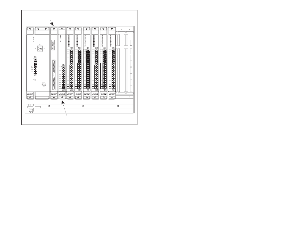
Page 21: Figure 4.4 ć module in a local rack
4Ć3
1
0
2
3
4
C1
5
6
7
C2
8
9
10
11
C3
12
13
14
15
C4
B
C
D E
F
G
1
2
3
6
7
8
B
C
D E
F
G
1
2
3
6
7
8
OK
275 W
POWER
SUPPLY
1
0
2
3
4
C1
5
6
7
C2
8
9
10
11
C3
12
13
14
15
C4
B
C
D E
F
G
1
2
3
6
7
8
1
0
2
3
4
C1
5
6
7
C2
8
9
10
11
C3
12
13
14
15
C4
B
C
D E
F
G
1
2
3
6
7
8
1
0
2
3
4
C1
5
6
7
C2
8
9
10
11
C3
12
13
14
15
C4
B
C
D E
F
G
1
2
3
6
7
8
120V
LINK
GND
L2
L1
FUSE
BATTERY
BACKĆUP
POWER ON
P S READY
SYSTEM READY
BLOWN FUSE
NORMAL
REMOTE
PROGRAM
57491
Processor Module
Module
B
C
D E
F
G
1
2
3
6
7
8
1
0
2
3
4
C1
5
6
7
C2
8
9
10
11
C3
12
13
14
15
C4
B
C
D E
F
G
1
2
3
6
7
8
1
0
2
3
4
C1
5
6
7
C2
8
9
10
11
C3
12
13
14
15
C4
B
C
D E
F
G
1
2
3
6
7
8
0
1
2
3
4
5
6
7
8
9
10
11
12
13
14
15
0
1
2
3
4
5
6
7
8
9
10
11
12
13
14
15
0
1
2
3
4
5
6
7
8
9
10
11
12
13
14
15
0
1
2
3
4
5
6
7
8
9
10
11
12
13
14
15
0
1
2
3
4
5
6
7
8
9
10
11
12
13
14
15
0
1
2
3
4
5
6
7
8
9
10
11
12
13
14
15
RESOLVER
INPUT
57C411
OK
P3
Figure 4.4 Ć Module in a Local Rack
4.2.1
Single Register Reference
Use this method to reference a 16Ćbit register as a single input.
Resolver input data, update period, and interrupt control registers are
typically referenced using this method. The symbolic name of each
register should be as meaningful as possible:
nnnnn IODEF SYMBOLIC_NAME%[ SLOT=s, REGISTER=r]
4.2.2
Bit Reference
Use this method to reference individual inputs on the module.
Common clock status and control bits are typically referenced using
this method. The symbolic name of each bit should be as meaningful
as possible:
nnnnn IODEF SYMBOLIC_NAME@[ SLOT=s, REGISTER=r, BIT=b]
where:
nnnnn Ć BASIC statement number. This number may range from
1Ć32767.