Place and connect shapes – Rockwell Automation Arena Basic Edition Users Guide User Manual
Page 59
4
•
U
SING
V
ISIO
AND
A
RENA
53
•
•
•
• •
4
• Usi
ng
V
isi
o a
nd
Are
na
Place and connect shapes
To define the process flow portion of your model, drag and drop flowchart shapes (e.g.,
Create, Process, Dispose) from the Process Simulation stencil into your drawing, just as
you would with other standard Visio stencils. Then, use the connectors from the Process
Simulation stencil to establish flow.
When connecting shapes, the Dynamic Connector is used for all except Decide and
Separate, which use special connectors to determine the type of each of the two possible
outgoing connections. The table below lists the shapes from which the connectors can
start (e.g., the True Connector can only start at a Decide shape).
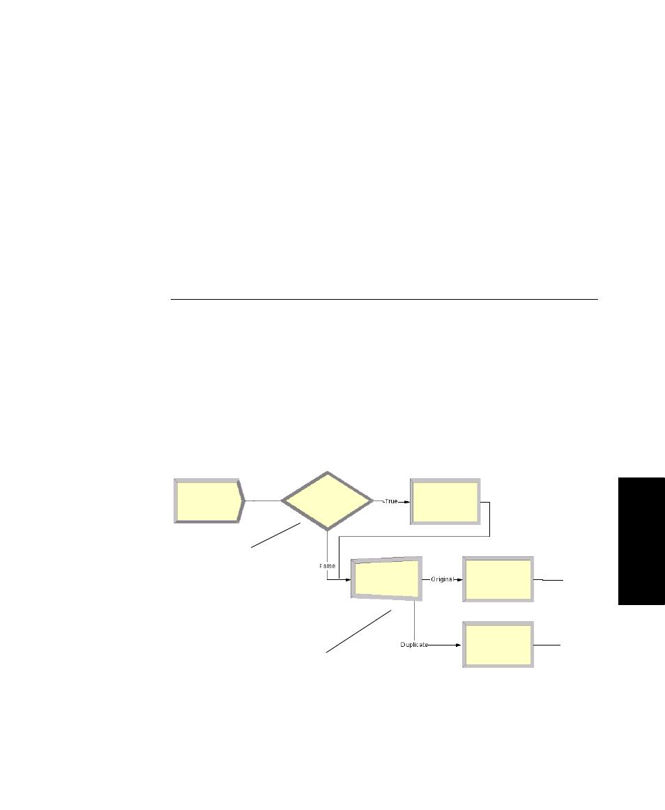
The sample flowchart below illustrates the use of these connectors, including the
Dynamic Connector, which is unlabeled.
Connector
Valid Starting Shape
True Connector
Decide
False Connector
Decide
Original Connector
Separate
Duplicate Connector
Separate
Dynamic Connector
Create, Process, Batch, Assign, Record
You can change the
Visio page layout or
size via the File >
Page Setup menu.
For many process
maps, a Standard
page size and Land-
scape orientation
work well.
Decide shape
(True and
False
connectors)
Separate shape
(Original and Duplicate
connectors)