Connector data, Iam power module features and indicators – Rockwell Automation 2094-BMxx-M Kinetix 6200 and Kinetix 6500 IAM and AM Power Modules Installation Instructions User Manual
Page 12
12 Kinetix 6200 and Kinetix 6500 IAM and AM Power Modules
Rockwell Automation Publication 2094-IN011D-EN-P - August 2013
Connector Data
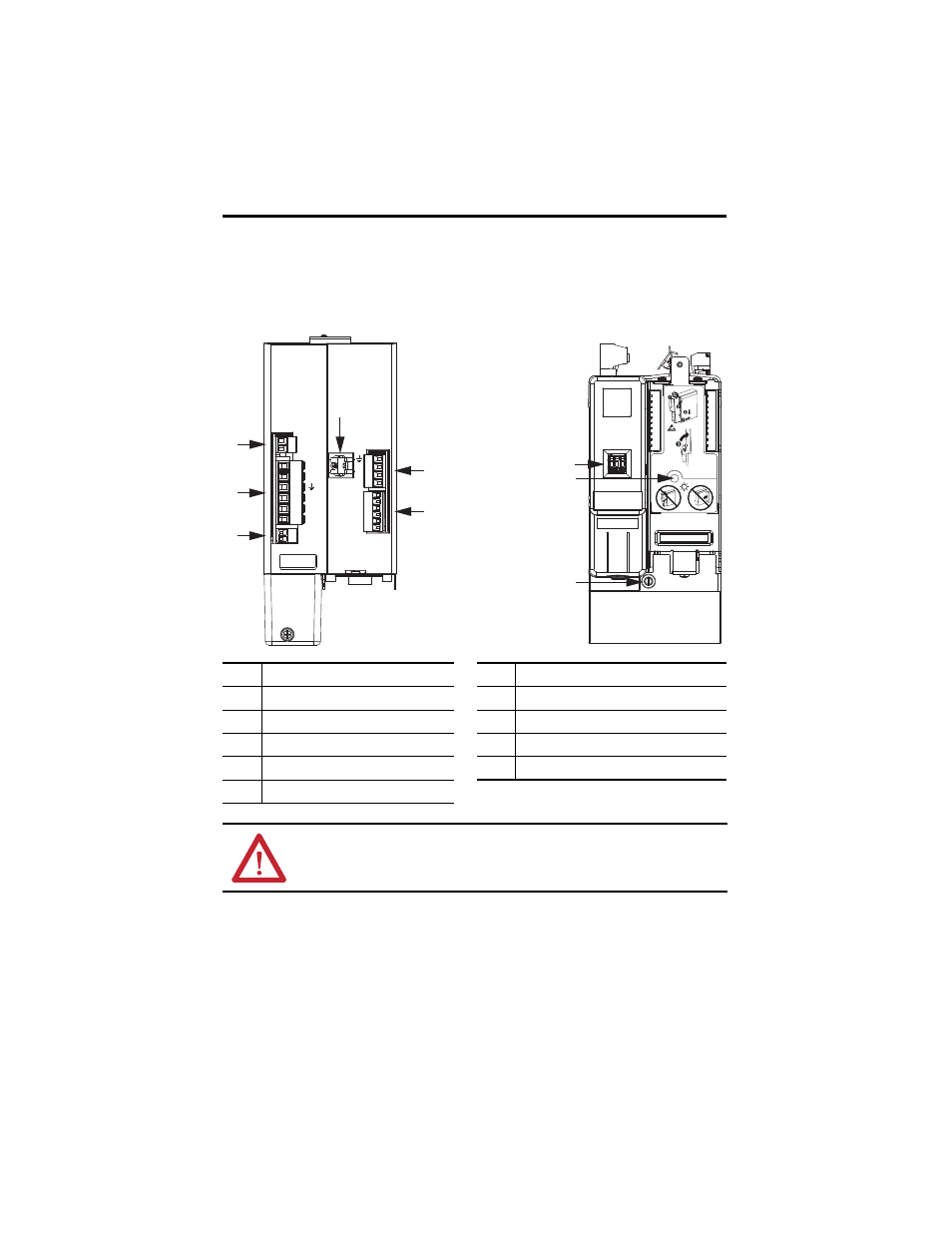
Use these illustrations to identify the IAM and AM power module features and indicators.
IAM Power Module Features and Indicators
Item
Description
Item
Description
1
Control power (CPD) connector
6
Motor/resistive brake (BC) connector
2
DC bus/AC input power (IPD) connector
7
Node address switch
3
Contactor Enable (CED) connector
8
Power-applied indicator
4
Motor cable shield clamp
9
Mounting screw
5
Motor power (MP) connector
ATTENTION: To avoid damage to equipment, do not mount your Bulletin 2094 control
module to the power module when the Power-applied indicator is on. Remove all input
power from the IAM power module before mounting the control module.
1 2
DC-
DC+
L3
L2
L1
CONT EN-
CONT EN+
CTRL 2
CTRL 1
1 2
1 2 3 4 5 6
W
V
U
MBRK -
MBRK +
COM
PWR
DBRK -
DBRK +
1 2 3 4
1 2 3 4 5 6
1
4
5
2
3
6
7
9
8
IAM Power Module, Top View
(2094-BC01-MP5-M is shown)
IAM Power Module, Front View
(2094-BC01-MP5-M is shown)