0 overview – Rockwell Automation 9329 Drive Application Software Inertia Comp Imperial Units User Manual
Page 8
FM – Inertia Compensation
Drive Application Software – page 8 of 28
3.0 Overview
The torque applied by the motor, in a web handling application, can be separated into three torque
components:
1. Strip Tension Torque
2. Inertia Torque
3. Losses Torque
The Inertia Compensation Function Module calculates inertia torque and losses torque.
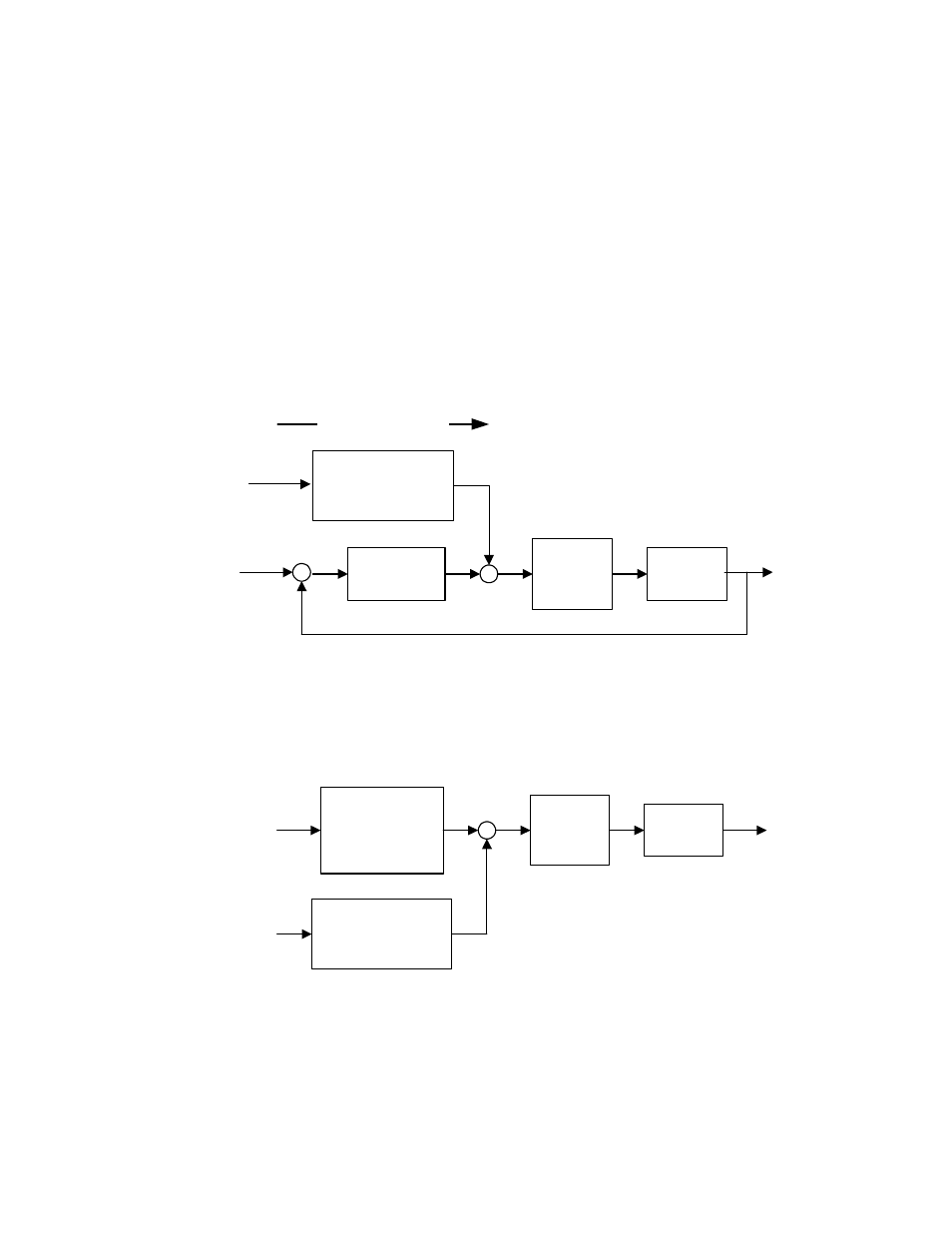
3.1 Feed Forward
Speed regulation, dancer position regulation and strip tension regulation can be improved by
feeding inertia and losses torque forward as a torque minor loop reference. The following
block diagram demonstrates how the Inertia Compensation Function Module can be used in
a feed forward path to improve speed regulation.
3.2 Tension-to-Torque Conversion
When strip tension is controlled indirectly by controlling motor torque, strip tension deviation
can be reduced by including inertia and losses torque in tension-to-torque conversion
calculations. The following block diagram demonstrates how the Inertia Compensation
Function Module can be used to convert tension reference to motor torque reference.
Tension
Reference
Inertia
Compensation
FM
+
Diameter &
Gear Ratio
Scaling
Actual
Strip
Tension
Line
Speed
Reference
+
Torque
Minor
Loop
Motor
Speed
Controller
+
-
FeedForward Path
Torque
Minor
Loop
+
Inertia
Compensation
FM
+
Line
Speed
Reference
Actual
Speed
Motor