4 jlosscomp routine – Rockwell Automation 9329 Drive Application Software Inertia Comp Imperial Units User Manual
Page 12
FM – Inertia Compensation
Drive Application Software – page 12 of 28
4.4 JLossComp Routine
Inertia torque is calculated by multiplying total reflected inertia by angular
acceleration:
α
⋅
=
J
T
where: T is torque
J
is total inertia
α
is angular acceleration
Angular acceleration is calculated from the rate of change of line speed using the
translational-to-rotational conversion constant and build-up ratio (normalized
diameter). Separate input parameters are provided for line speed reference and line
speed reference rate. If necessary, the JLossComp routine can calculate the line
speed reference rate from line speed reference by differentiating the line speed
reference input.
If the Inertia Compensation Function Module is not used for a center driven winder,
the build-up ratio is typically set equal to one.
Two inertia compensation gains (JGainQuad1Quad2 and JGainQuad3Quad4) can be
used to adjust the calculated inertia torque in two of four operational quadrants.
These gains are typically set equal to one, but can be adjusted slightly to reduce strip
tension deviations during line speed changes.
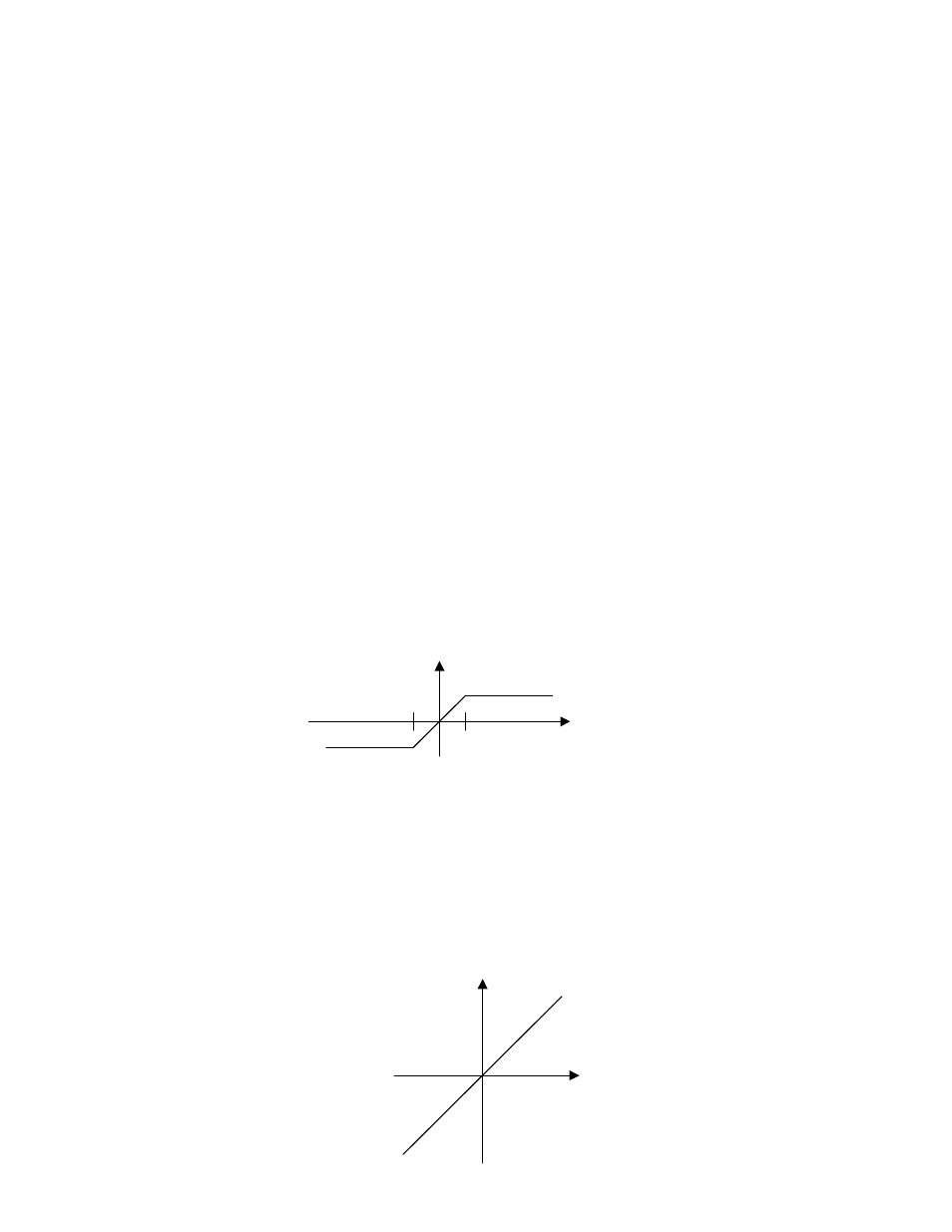
Friction torque is calculated using the following curve:
When the rotational speed reference reaches +/- 2 RPM, the output is a fixed torque,
representing a kinetic friction torque component. A static friction component is not
included.
Windage torque requirements dictate that losses due to rotational speed increase as
the square of speed. In practice for typical winding applications, an approximation of
windage losses has proved more beneficial and simpler to configure. For these
reasons the windage losses compensation has been applied as directly proportional
to rotational speed reference and is calculated using the following curve:
Motor
Speed
[RPM]
Friction
Torque
[%]
+2
-2
Motor
Speed
[RPM]
Windage
Torque [%]