Plc string variables – Rockwell Automation 2706-F11J_F11JC_F21J_F21JC DL50 INSTALLATION MANUAL User Manual
Page 87
Chapter 6
Slave Mode Operation / Examples
6–23
PLC String Variables
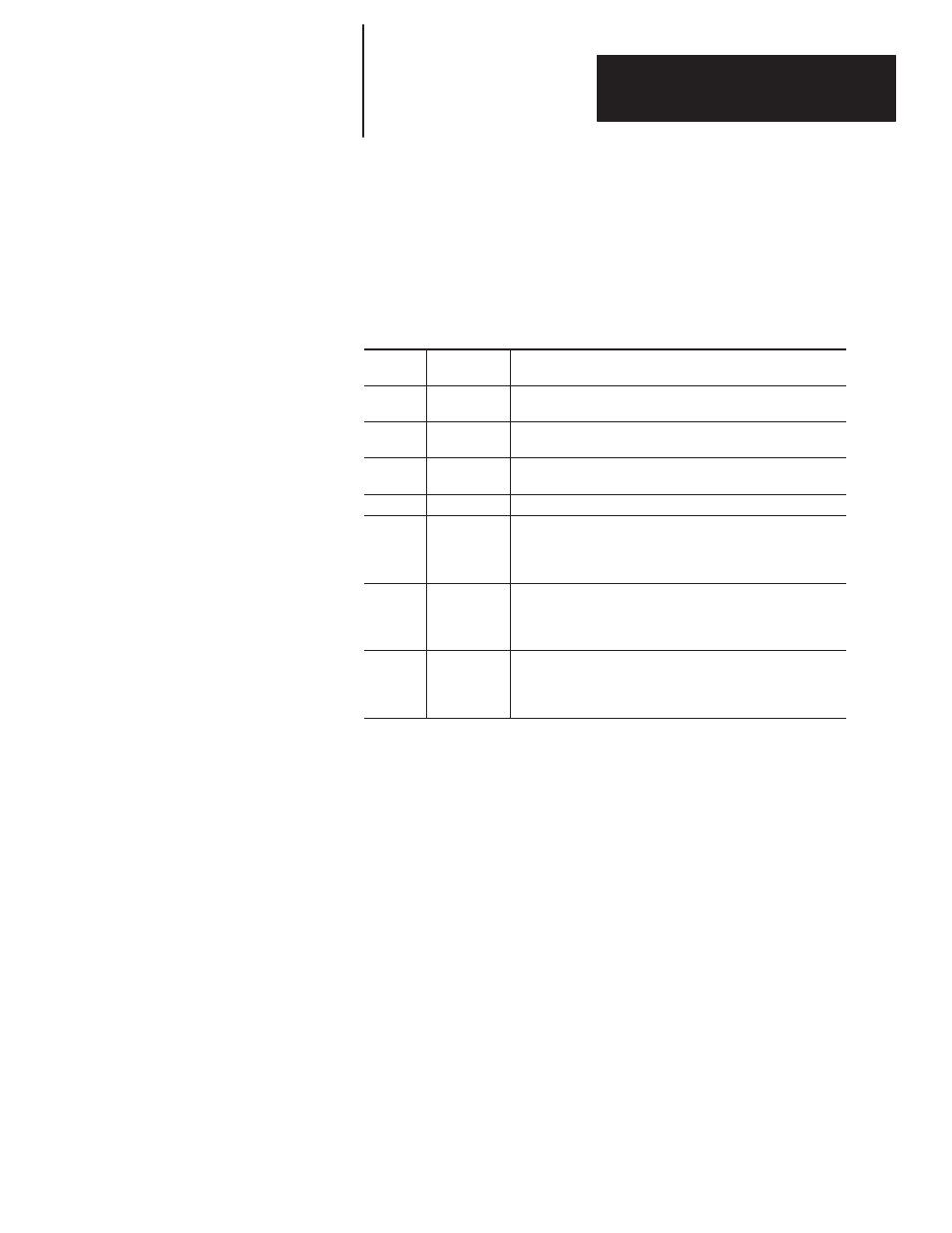
For this example, processor memory file #12 is set up as a string file which
contains the parts needed to form a message packet for a DL50 in Duplex
mode. Table 6.G has the variables for any Duplex mode communication, and
Table 6.H shows the strings for this example.
Table 6.G
Variables for Duplex Protocol and Their Functions
Memory
Location
Symbol
Description
ST12:0
MSG_SEND
The message which is built by the PLC and is actually sent out
to the DL50 through CH0
ST12:1
VARIABLE
The converted integer sample variable being appended to the
message
ST12:2
PRE_TEXT
The duplex protocol control byte (Field 1) and color code
(F11JC and F21JC only)
ST12:3
TEXT
The message text
ST12:4
F3_F4_F5
Fields 3, 4, and 5 of the duplex protocol
Field 3 determines the slave address
Field 4 determines the line number
Field 5 is \OD to produce a carriage return
ST12:5
F6_B123
The three bytes of field 6 of the duplex protocol. This dield
controls the display mode, speed, and relay for each message.
Use the Duplex Field 6 Worksheet to determine hex values for
desired display operation.
ST12:6
CHECKSUM
Dummy checksum bytes appended to the end of the message.
Their actual value is not important, since the checksum
checking must be disabled on the DL50.
(Note: These bytes MUST NOT equal 13 or 18 decimal.)