Annunciation relay connections – Rockwell Automation 2706-F11J_F11JC_F21J_F21JC DL50 INSTALLATION MANUAL User Manual
Page 36
Chapter 4
Installing the DL50
4–11
1. Connect ground wire to the chassis grounding terminal. Then verify that
the factory installed earth ground wire is connected between the chassis
PE (Protective Earth) terminal and the earth ground terminal on the power
input connector.
Note: If the power lines enter the left side of the display, route the AC
lines through the cable guides on the upper part of the display. Route the
communication lines through the cable guides on the bottom half of the
display.
2. Connect input power lines, L1 and L2N. Do not apply power until all
connections have been made
3. Connect communications lines as described in the following sections.
4. Apply power and verify power-up messages as shown in Chapter 3.
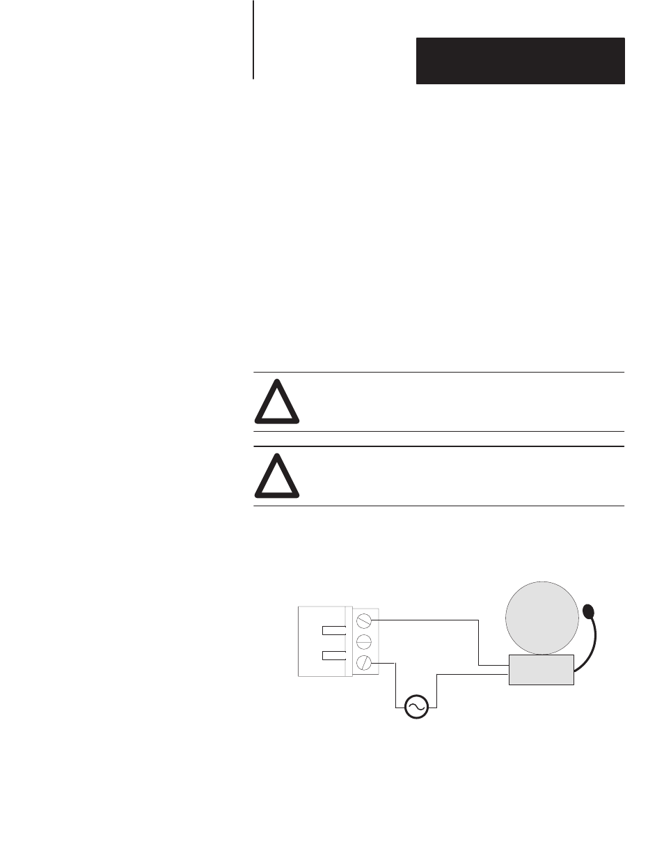
Figure 4.8 shows a typical connection between the annunciation relay and an
annunciator.
!
ATTENTION: Do not use the relay for control purposes. Use
relay for annunciator only. Failure to follow this warning could
result in unexpected switching of control circuits.
!
ATTENTION: When power is removed, the annunciator will be
energized if the normally closed outputs are used.
Figure 4.8
Annunciation Relay Connections (Normally Open)
ALARM
Relay is rated for:
3A @ 240V AC resistive load
3A @ 30V DC resistive load
NO = Normally Open
NC = Normally Closed
COM = Common
DL50
RELAY TERMINALS
NO-
NC-
COM-
RELAY
1
2
3
Annunciation Relay
Connections