Rockwell Automation 2706-F11J_F11JC_F21J_F21JC DL50 INSTALLATION MANUAL User Manual
Page 40
Chapter 4
Installing the DL50
4–15
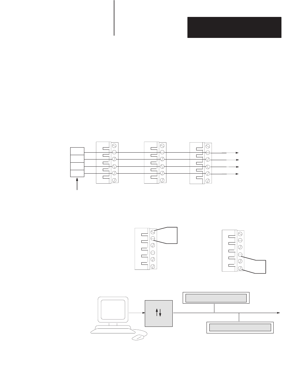
Figure 4.12
shows a typical connection between a host device RSĆ485 port and
DL50 displays. We recommend that you use Belden 9842 cable.
Note that pin or terminal numbers are not shown for the host device. This is
because the terminal numbers vary for different products. For actual pin
numbers, refer to the appropriate host device product literature.
We recommend that you connect the shield to ground at one end only, as
shown.
Figure 4.12
RS-485 Connections
Note: Some devices require that certain
hardware handshaking lines be asserted.
Refer to the applicable product literature.
RS-485 (+)
RS-485 (-)
To
Other
DL50s
DL50
RS-485
TERMINALS
+
–
SHLD
COM
Common
Shield
1
6
2
3
4
5
+
–
SHLD
COM
+
–
SHLD
COM
1
2
3
4
5
6
+
–
SHLD
COM
E. GND
TERM
HOST
TERMINALS
DL50
RS-485
TERMINALS
DL50
RS-485
TERMINALS
2
3
4
5
2
3
4
5
Connect shield (terminal #2) to ground
(terminal #1) at any one node (only) on
RS-485 Network
1
2
3
4
5
6
+
–
SHLD
COM
E. GND
TERM
Terminate the network at the last device.
Terminate a DL50 by connecting RS-485 +
(terminal #4) to
TERM (terminal #6).
Shield
Grounding
Network
Termination
BLACK BOX
LD485A-MP
DL50 DISPLAY
DL50 DISPLAY
To Other DL50 Displays
Note: RS-232 devices such as
personal computers can communi-
cate through the DL50 RS-485
port using an RS-232
! RS-485
converter such as a Black Box
TM
LD-485A-MP.
1
6
1
6
RS-232
RS-485
RS-232
RS-485