Rockwell Automation 1771-ASB/E Remote I/O Adapter User Manual User Manual
Page 73
Settings for 1771–AS and 1771–ASB Series A, B, C and D Remote I/O Adapters
B–11
Publication 1771ĆUM001A-US-P - February 2000
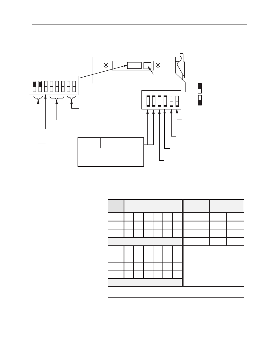
Figure B.11
Module Switch Assembly Settings for 1771-ASB series C
and D Adapters for PLCĆ5 Family Processors With
Complementary I/O
1 2 3 4 5 6 7 8
O
N
O
F
F
First I/O group number
(Table B.H)
I/O rack number
(Table B.H)
Address Switch Assembly
(S1)
Switch Assembly
(S2)
Pressed in at top
Closed (ON)
Pressed in at bottom
Open (OFF)
Always ON
ON Ć Primary chassis
OFF Ć Complementary chassis
ON Ć Primary chassis
OFF Ć Complementary chassis
O
N
O
F
F
1 2 3 4
5 6
Link Response Ć on for series B emulation
Scan Ć on for all but last 4 slots
off for all slots
off for unrestricted
10801ĆI
Switch Position
1
2
ON OFF 57.6K Baud Ć 10,000ft
OFF OFF 115.2K Baud Ć 5,000ft
ON ON
Not Used
Maximum I/O
chassis distance(see note)
OFF ON
230.4K Baud Ć 2,500ft
Note: PLCĆ5/15 and 5/25 processors
operate at 57.6K baud only.
Off
Table B.H
I/O Rack Selection for PLCĆ5 Family Processors with
Complementary I/O
I/O
Rack #
Switch
1
2
3
4
5
6
1st I/O Group
Number
Switch Selections
7
8
01
On
On
On
On
On
Off
0
On
On
02
On
On
On
On
Off
On
2
On
Off
03
On
On
On
On
Off
Off
4
Off
On
6
Off
Off
04
On
On
On
Off
On
On
05
On
On
On
Off
On
Off
06
On
On
On
Off
Off
On
07
On
On
On
Off
Off
Off
See note below
Note:
PLCĆ5/11 can scan rack 03.
PLCĆ5/20, PLCĆ5/30, PLCĆ5/40, PLCĆ5/60 can scan racks 01Ć07.