1/2-slot addressing, 1/2ć slot addressing, Switch 5 to the off position – Rockwell Automation 1771-ASB/E Remote I/O Adapter User Manual User Manual
Page 49
3–19
Addressing Modes for Your Remote I/O
Publication 1771-UM001A-US-P - February 2000
Definition: The processor addresses one-half of an I/O module slot as
one I/O group.
Concept: The physical address of each I/O slot corresponds to two
input and two output image table words. The type of module you
install (8-, 16-, or 32-point) determines the number of bits in these
words that are used.
You select 1/2-slot addressing by setting switches 5 and 6 of the I/O
chassis backplane switch assembly:
•
switch 5 to the OFF position
•
switch 6 to the ON position
With 1/2-slot addressing, since 32 inputs bits AND 32 output bits are
available in the processor’s image table for each I/O group, you can
mix 8, 16 and 32-point I/O modules in any order in the I/O chassis.
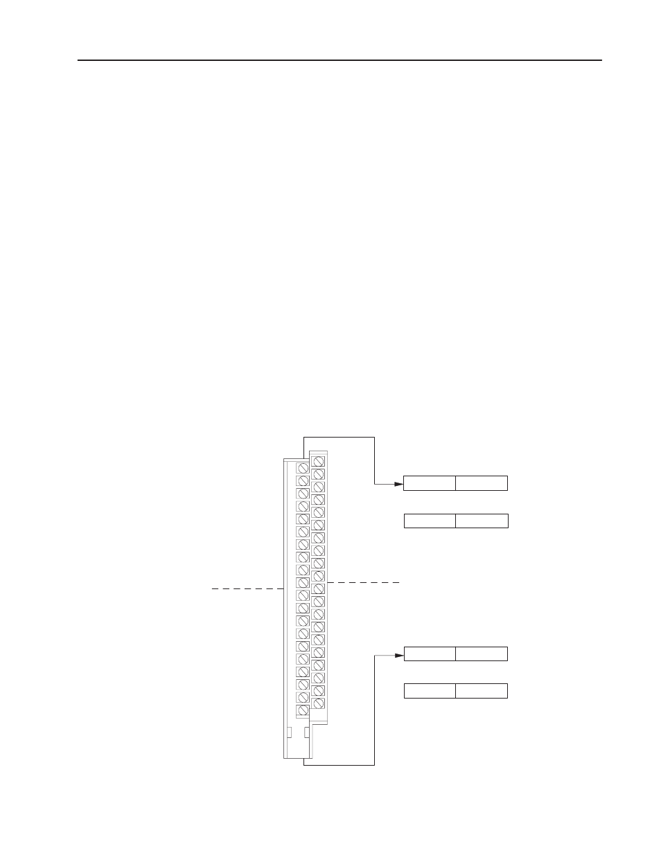
Figure 3.17 illustrates the 1/2-slot addressing concept with a 32-point
I/O module. A 32-point I/O module (with 1/2-slot I/O groups) uses
two words of the image table. When you use 8 and 16-point I/O
modules with 1/2-slot addressing, you get fewer total I/O points.
Figure 3.17
1/2Ćslot Addressing Concept
In p u t W o rd 0
O u tp u t W o rd 0
Im a g e T a b le
W o rd s A llo ca te d
fo r I/O G ro u p 0
In p u t W o rd 1
O u tp u t W o rd 1
Im a g e T a b le
W o rd s A llo ca te d
fo r I/O G ro u p 1
14259
#
0 0
0 2
0 4
0 6
-
1 0
1 2
1 4
1 6
-
0 0
0 2
0 4
0 6
-
1 0
1 2
1 4
1 6
-
#
0 1
0 3
0 5
0 7
-
1 1
1 3
1 5
1 7
-
0 1
0 3
0 5
0 7
-
1 1
1 3
1 5
1 7
-
U n u se d
1 7
0
1 0
7
1 7
1 0
0
7
1 7
1 0
0
7
1 7
1 0
0
7
U n u se d
3 2 -p o i n t In p u t M o d u le
1 /2 -slo t
I/O G ro u p
0
1 /2 -slo t
I/O G ro u p
0
1 /2 -slo t
I/O G ro u p
1
1 /2 -slo t
I/O G ro u p
1
In p u t
In p u t
1/2Ć Slot Addressing