Setting the i/o chassis switches, Setting the backplane switch assembly – Rockwell Automation 1771-ASB/E Remote I/O Adapter User Manual User Manual
Page 23
2–9
Installing Your Module
Publication 1771-UM001A-US-P - February 2000
After setting the adapter module switch assemblies, you must also
•
set the I/O chassis backplane switches
Setting the Backplane Switch Assembly
The backplane switch assembly is located on the backplane of the
I/O chassis. You use it to select:
•
the last state of all outputs
•
the processor restart lockout feature
•
1/2-, 1- or 2-slot addressing
•
the last chassis in the I/O system (for PLC-2 family processors)
Refer to the table below for backplane switch setting illustrations for
the various processors.
For Processor:
Refer to:
PLCĆ2
Figure 2.8, page 2-9
PLCĆ3
Figure 2.9, page 2-10
PLCĆ5
Figure 2.10, page 2-10
PLCĆ5 remote configuration
Figure 2.11, page 2-11
PLCĆ5/250
Figure 2.12, page 2-11
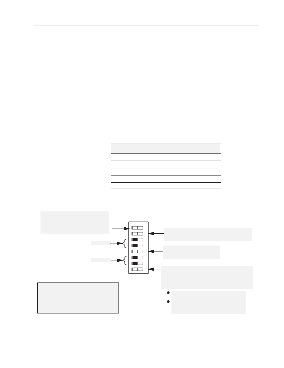
Figure 2.8
I/O Chassis Backplane Switch Assembly Settings for
Remote Adapter Module in PLCĆ2 Family Processor System
Processor Restart Lockout Ć
When ON, processor can restart I/O chassis
When OFF, I/O chassis must be restarted at the chassis.
Addressing Switch Ć
ON Ć 1Ćslot addressingselected
OFF Ć 2Ćslot addressingselected
Last State Switch Ć
When ON, outputs of this chassis remain
in last state.
When OFF, outputs of this I/O chassis are
deenergized when a fault is detected.
Always OFF
Last Chassis Switch Ć
ON Ć Chassis does not contain the highest numbered I/O
group for the associated rack number
OFF Ć Chassis does contain the highest numbered I/O
group for the associated rack number
If you have only a primary chassis, set this
switch to OFF.
If you have both primary and complementary
chassis, set the primary chassis to ON and the
complementary chassis to OFF.
1080
ATTENTION: Set switch 1 to the OFF position
to deenergize outputs wired to this chassis when a
fault is detected. If switch 1 is set to the ON
position, outputs connected to this chassis remain
in their last state when a fault occurs and machine
motion may continue after fault detection.
O
O
12
3
456
7
8
N
F
F
Always OFF
Setting the I/O Chassis
Switches