Rockwell Automation 1792D-4BV4D ArmorBlock MaXum 4 Input/4 Output Module with 8 Connectors, Series B I.I. User Manual
Page 10
10 ArmorBlock MaXum 4 Input / 4 Output Module with 8 Connectors, Series B
Publication 1792D-IN050A-EN-P - February 2001
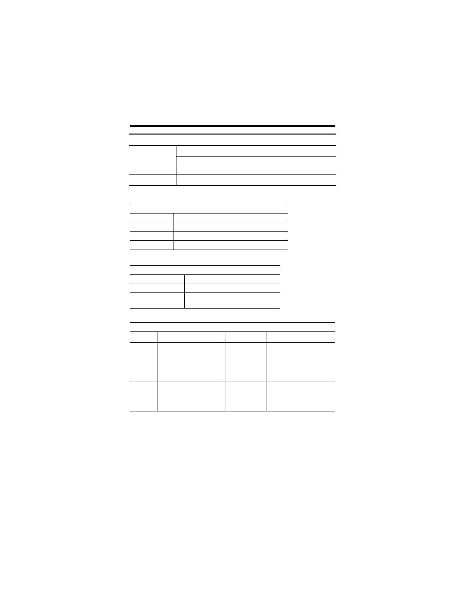
The following table describes logic status indicators.
The following table describes auxiliary power indicators.
The following table describes individual I/O status indicators.
For more information on indications see the Technical Data
publication 1792-TD001B-EN-P.
Net/Mod Status Indicator (continued)
Solid Red
Unrecoverable fault
Communication failure - duplicate node address present or incorrect
baud rate
Green to Red to Off At powerup only - LED test
Logic Status Indicators
State
Status
Off
Logic is disabled
Solid Green
Logic is enabled
Flashing Green
Local forces are applied and local logic is enabled
Auxiliary Power
Indication
Status
None
No Auxiliary Power
Green
Solid
Auxiliary Power Present
I/O Status Indicators
Function
Module Status Indicator
Point Indicator
Condition
Outputs
Green
Green
Module Status blink red
Module Status blink red
Module Status blink red
Module Status blink red
None
Yellow
Orange
Red
Orange
Red
Output not energized
Output energized
Output shorted-auto restart
Output shorted-latching
Output no load-auto restart
Output no load-latching
Inputs
Green
Green
Module Status blink red
Module Status blink red
None
Yellow
Red
Blink red
No valid input
Valid input
Short on input connector
Off wire on input connector