Mount the module to a panel – Rockwell Automation 1769-IT6 Compact I/O Thermocouple/mV Input Module User Manual
Page 9
Compact I/O Thermocouple/mV Input Module 9
Publication 1769-IN026C-EN-P - February 2010
Mount the Module to a Panel
Mount the module to a panel by using two screws per module. Use M4 or #8 panhead screws.
Mounting screws are required on every module.
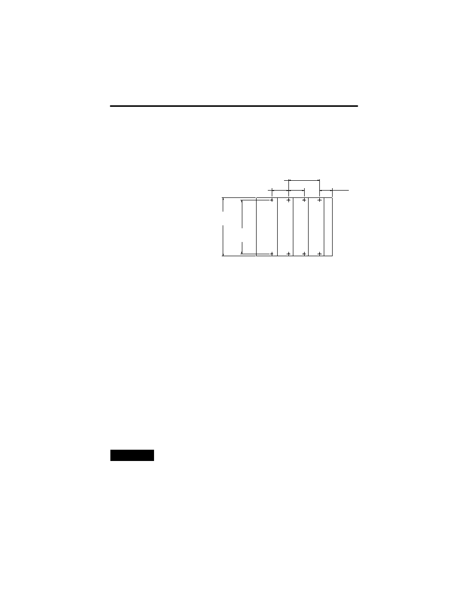
Mount the Module to a Panel by Using the Dimensional Template
Mount the Module to a Panel by Using Modules as a Template
This procedure uses the assembled modules as a template for drilling holes in the panel.
If you have sophisticated panel-mounting equipment, you can use the dimensional template
above. Due to module-mounting hole tolerance, it is important to follow these procedures.
1. On a clean work surface, assemble no more than three modules.
2. Using the assembled modules as a template, carefully mark the center of all
module-mounting holes on the panel.
3. Return the assembled modules to the clean work surface, including any previously
mounted modules.
4. Drill and tap the mounting holes for the recommended M4 or #8 screw.
5. Place the modules back on the panel and check for proper hole alignment.
6. Attach the modules to the panel by using the mounting screws.
7. Repeat these steps for any remaining modules.
TIP
If you are mounting more modules, mount only the last one of this group and put the
others aside. This reduces remounting time during drilling and tapping of the next group.
Hos
t Cont
ro
ller
Com
pact
I/
O
Com
pact
I/
O
Com
pact
I/
O
End Cap
132 (5.197)
122.6 ±0.2
(4.826 ±0.008)
35
(1.38)
28.5
(1.12)
For more than 2 modules: (number of modules-1) x 35 mm (1.38 in.).
All dimensions are in mm (in.). Hole spacing
tolerance: ±0.4 mm (0.016 in.).
Refer to host controller documentation for this dimension.