Rockwell Automation 1785-BCM_BEM, D17856.5.4 PLC-5 Backup Communication Module User Manual User Manual
Page 60
Installing Your 1785-BEM Module
Chapter 4
4-17
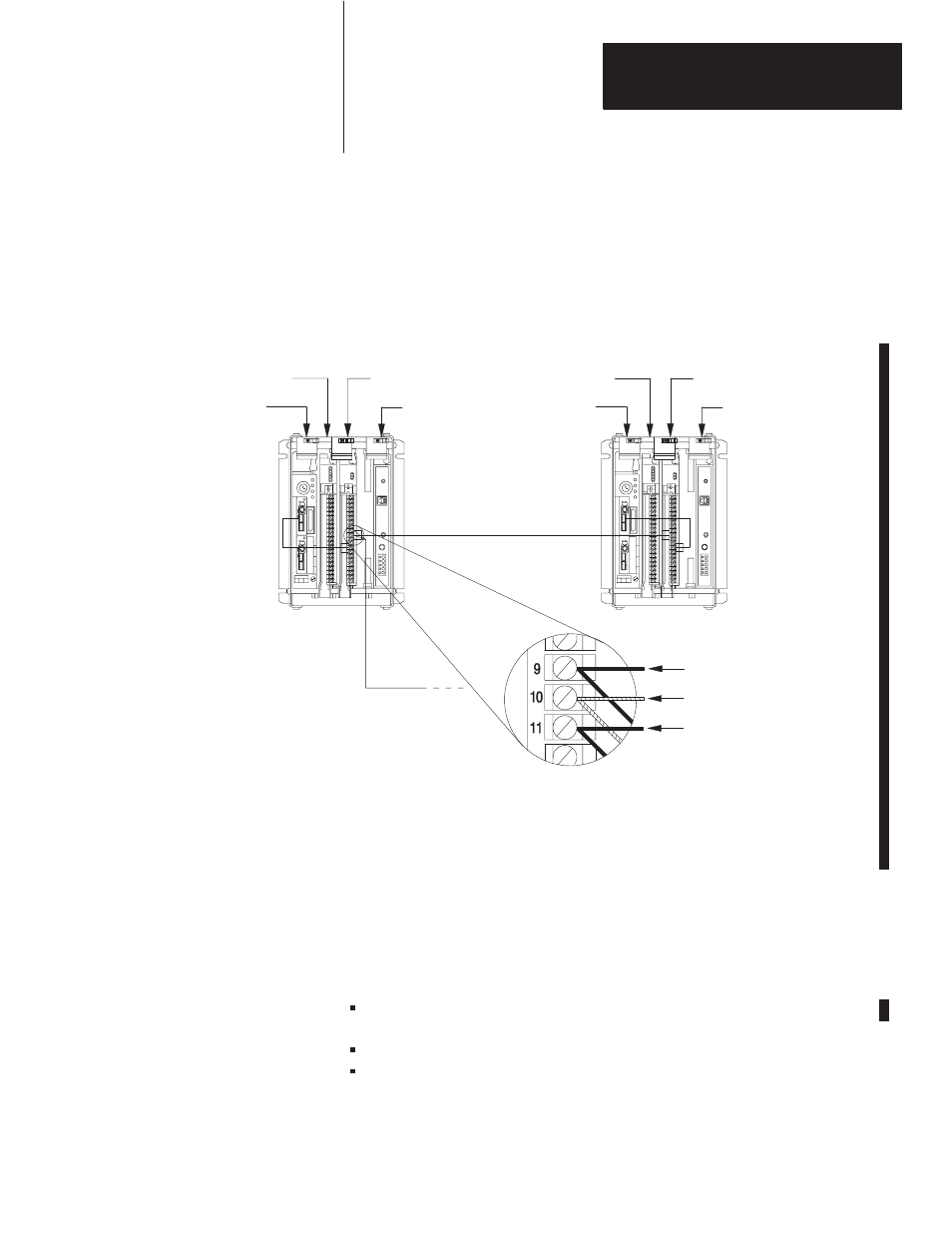
5.
Connect the 1770-CD cable from the Data Highway Plus network or
Remote I/O link to 9, 10, and 11 on the wiring arm of one of the
1785-BEM modules as shown in Figure 4.11.
Figure 4.11
Channel 2A Connections Added Between a 1785-BEM Module
and Data Highway Plus Network or Remote I/O Link
1771 –P4S
Power Supply
1771 –P4S
Power Supply
Local I/O Chassis
Local I/O Chassis
Data Highway Plus – connect the signal conductors with Clear, Shield, and Blue insulation to
terminals 9, 10, and 11 of 1785 –BEM modules respectively.
Remote I/O – connect the signal conductors with Blue, Shield, and Clear insulation to terminals 9, 10, and 11 of
1785 –BEM modules respectively.
Data Highway Plus
network or Remote I/O
19092
Channel 2A
See Note
Shield
See Note
Wire channel for either Data Highway Plus or Remote I/O.
1785-BCM module
1785-BEM module
PLC-5/40, -5/60, -5/80
1785-BCM module
1785-BEM module
PLC-5/40, -5/60, -5/80
Making Channel 2B Connections
Figure 4.12 shows the Channel 2B connections you must make for your
PLC-5 backup system. These connections are between the:
PLC-5/40, PLC-5/60, or PLC-5/80 processor and the
1785-BEM module
two 1785-BEM modules
1785-BEM module and Data Highway Plus or Remote I/O link