Installing your plc-5 backup system chapter 3, Keying your i/o chassis, Setting the 1785-bcm series b switch assemblies – Rockwell Automation 1785-BCM_BEM, D17856.5.4 PLC-5 Backup Communication Module User Manual User Manual
Page 29
Installing Your PLC-5 Backup System
Chapter 3
3-6
Keying Your I/O Chassis
Use the plastic keying bands, shipped with each I/O chassis, to key the
chassis slot to accept only the 1785-BCM module.
The module circuit board is slotted in two places on the rear edge. The
position of the keying bands on the backplane connector must correspond
to these slots to allow insertion of the module. You can key any connector
in an I/O chassis to receive this module except for the left-most connector
reserved for the processor modules.
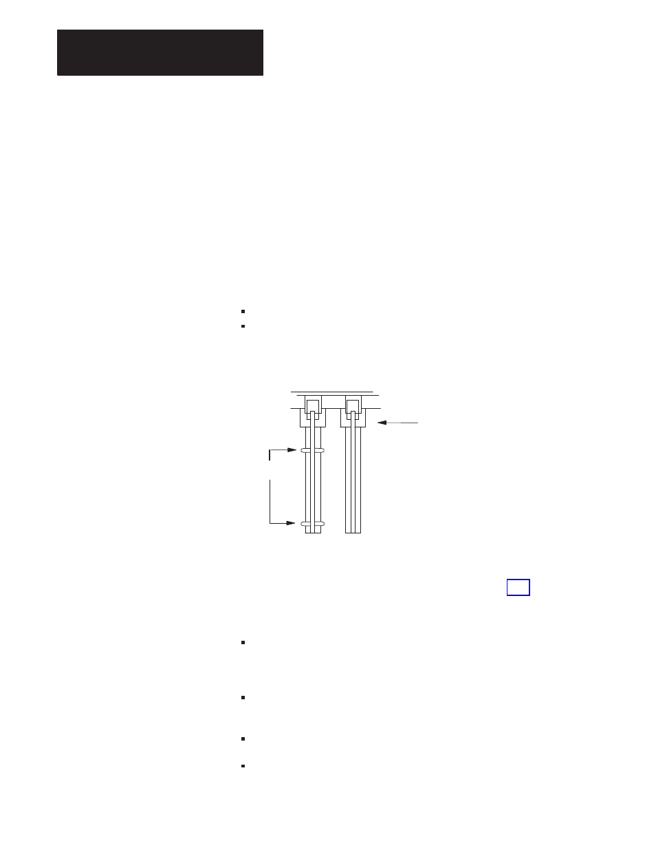
Place keying bands between the following numbers labeled on the
backplane connector (Figure 3.2):
Between 8 and 10
Between 34 and 36
Figure 3.2
Keying Positions
2
4
6
8
10
12
14
16
18
20
22
24
26
28
30
32
34
36
2
4
6
8
10
12
14
16
18
20
22
24
26
28
30
32
34
36
Keying bands
Backplane Connectors
11052I
Setting the 1785-BCM Series B Switch Assemblies
The switch assembly SW1, located at the top of the 1785-BCM module,
has four switches as shown in Figure 3.3. Refer to Table 3.E for
instructions on setting the four switches. The functions of the four switches
are:
Switch 1 indicates to the 1785-BCM series B module whether the other
1785-BCM module is a series A or a series B module. If it is a series A
module, functions of switches 2 through 4 will not apply.
Switch 2 selects the Fast Data-Transfer mode from the secondary
module to the secondary processor (1785-BCM series B module only).
Switch 3 is not used.
Switch 4 is not used.