Output data file – Rockwell Automation 1769-IF4FXOF2F Compact Combination Fast Analog I/O Module User Manual
Page 39
Publication 1769-UM019A-EN-P - October 2008
39
Module Data, Status, and Channel Configuration Chapter 3
Output Data File
The output data table lets you write analog output data and unlatch
command data to the module with the control program and bit access.
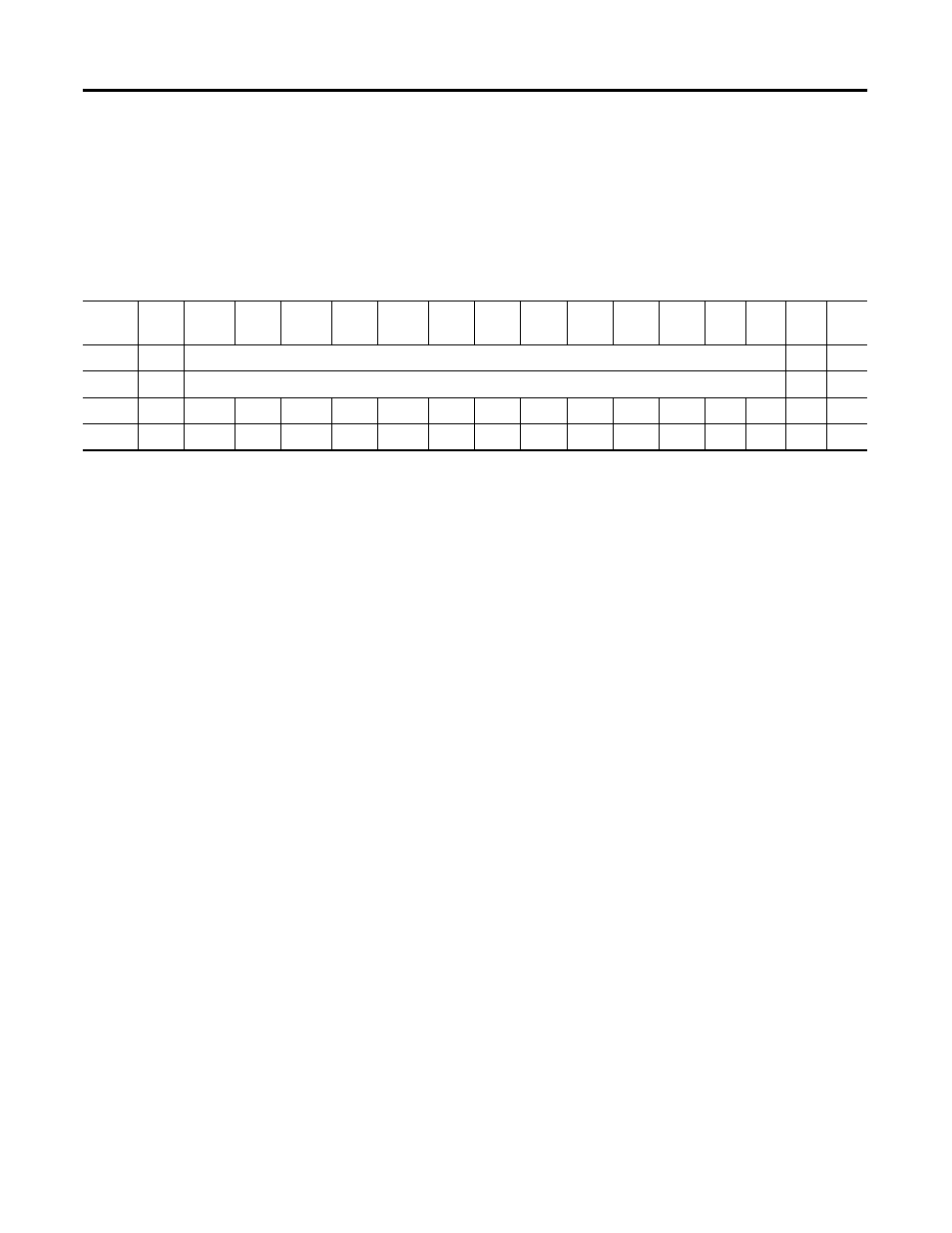
The data table structure is shown in the table below. For each
module, slot x, words 0 and 1 in the output data file contain the digital
values of the data to be converted to analog signals by the module
outputs. The most significant bit (MSB) is the sign bit, in two’s
complement format. ‘Nu’ indicates not used with the bit set to zero.
Cancel Input Alarm Control Bits (CLL0…CLL3 and CLH0…CLH3)
These bits are written during Run mode to cancel any latched low-
and high-process alarms. The alarm is unlatched when the unlatch bit
is set (1) and the alarm condition no longer exists. If the alarm
condition persists, then the unlatch bit has no effect until the alarm
condition no longer exists. You need to keep the unlatch bit set until
verification from the appropriate input-channel status word that the
alarm status bit has cleared (0). Then you need to reset (0) the unlatch
bit. The module will not latch an alarm condition if a transition from
‘no alarm’ to ‘alarm’ occurs while a channel’s cancel latch bit is set.
Cancel Output Clamp Flag Control Bits (CLO0…CLO1 and
CHO0…CHO1)
These bits are written during Run mode to cancel any latched low and
high clamp status bits. The status bit is unlatched when the unlatch bit
is set (1) and the clamp condition no longer exists. If the clamp
condition persists, then the unlatch bit has no effect until the clamp
condition no longer exists. You need to keep the unlatch bit set until
verification from the appropriate output-channel status word that the
clamp status bit has cleared (0). Then, you need to reset (0) the
unlatch bit. The module will not latch a clamp status bit if a transition
from no alarm to alarm occurs while a channel’s cancel latch bit is set.
Word/
Bit
15
14
13
12
11
10
09
08
07
06
05
04
03
02
01
00
Word 0 SGN
Analog Output Data Channel 0
0
0
Word 1 SGN
Analog Output Data Channel 1
0
0
Word 2 Nu
Nu
Nu
Nu
Nu
Nu
Nu
Nu
CLI3
CHI3
CLI2
CHI2
CLI1
CHI1 CLI0
CHI0
Word 3 Nu
Nu
Nu
Nu
Nu
Nu
Nu
Nu
Nu
Nu
Nu
Nu
CLO1 CHO1 CLO0 CHO0