Module addressing, Input image – Rockwell Automation 1769-IF4FXOF2F Compact Combination Fast Analog I/O Module User Manual
Page 34
34
Publication 1769-UM019A-EN-P - October 2008
Chapter 3 Module Data, Status, and Channel Configuration
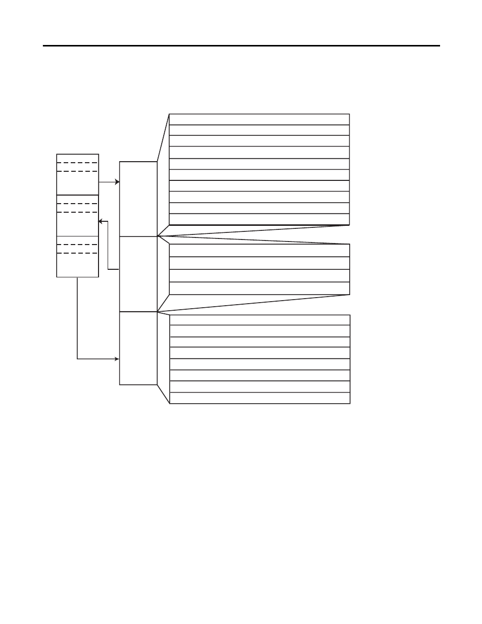
Module Addressing
This memory map shows the output, input, and configuration tables
for the module.
Memory Map
Input Image
The input image file represents data words and status bits. Input
words 0…3 hold the input data that represents the value of the analog
inputs for channels 0…3. These data words are valid only when the
channel is enabled and there are no errors. If time stamping is
enabled, Word 4 in the input data file contains the time stamp value
that corresponds to the module's last input-data sampling period.
Input words 5 and 6 hold the general status bits for each input
channel as well as the high and low alarm and over-range and
under-range bits. To receive valid status information, the input
channel must be enabled.
Slot e
Input Image
File
Output Image
File
Configuration
File
Slot e
Slot e
Input
Image
10 Words
Output
Image
4 Words
Configuration
File
42 Words
Output Channel 1 Configuration Words
Words 34…41
Input Channel 2 Configuration Words
Words 14…19
Output Channel 1 Data Word
Word 1
Channel 0 Data Word
Word 0
Input Channel 1 Configuration Words
Words 8…13
Input Channel 0 Configuration Words
Words 2…7
Word 2
Time Stamp Value Word
Word 4
Channel 2 Data Word
Word 2
General Input Status Bits
Word 5, bits 0…3
Input Alarm and Range Status Bits
Word 6
Bit 0
Output Range Status Bits
Data Echo Output Channel 0
Data Echo Output Channel 1
Word 7
Word 8
Word 9
Cancel Input Alarm Latch Bits
Bit 15
Channel 1 Data Word
Word 1
Channel 3 Data Word
Word 3
Output Channel 0 Data Word
Word 0
Word 3
Cancel Output Clamp Latch Bits
Enable Time Stamp
Word 1, bit 15
Real Time Sample Rate
Word 0
Input Channel 3 Configuration Words
Words 20…25
Output Channel 0 Configuration Words
Words 26…33