Rockwell Automation 1771-KA2 Communication Adapter Module User Manual
Page 90
Command Initiation, Execution, and
Monitoring
Chapter 7
7-18
to detect such a condition; the simplest of these methods uses an
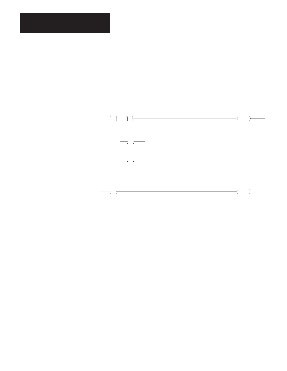
ON-DELAY timer. Figure 7.9 shows typical rungs that can be
programmed for this purpose.
Figure 7.9
Typical User-Programmed Timeout
033 12
/
Remote Fault
TON
060
0.1
032 12
Start
01002
060 15
Timed Bit
Indicator
Output
032 02
/
PR 100
AC 000
033 02
/
Local Fault
Done
In the first rung of this figure, timer 060 times the interval between the
setting of the START bit for a command and the DONE, LOCAL FAULT,
or REMOTE FAULT response of the module. If no response is received
within the preset interval of this timer, here 10 seconds, a fault may be
indicated and bit 06015 set ON. The second rung examines this bit to turn
on a warning indicator. Depending on the individual application, this bit
could also be used to enable or disable various parts of the program.
The preset value of this programmed TON instruction is not critical. For
this type of backup monitoring, the programmed preset must exceed the
timeout preset interval entered as a code in the header rung. (Remember
that the automatic timeout of the module gives a LOCAL FAULT
response to a command, which would indicate normal module/processor
communication, but faulted communication with some other station.)
As with automatic timeout preset monitoring, a user-programmed timeout
is useful as a backup to the other monitoring functions of the