Rockwell Automation 1771-KA2 Communication Adapter Module User Manual
Page 113
Start–up and Troubleshooting
Chapter 9
9-11
These rungs send the command continuously, as long as the ZCL area is
enabled. As a quick check of this continuous command execution and
completion, another rung can be added to the test rungs within the ZCL
area. This rung examines the START bit as the input condition to a
counter, as shown in Figure 9.6. Using this optional counter, you can
verify that the command is being executed continuously. To use this
optional counter, insert this additional rung within the ZCL area, between
rungs 3 and 4.
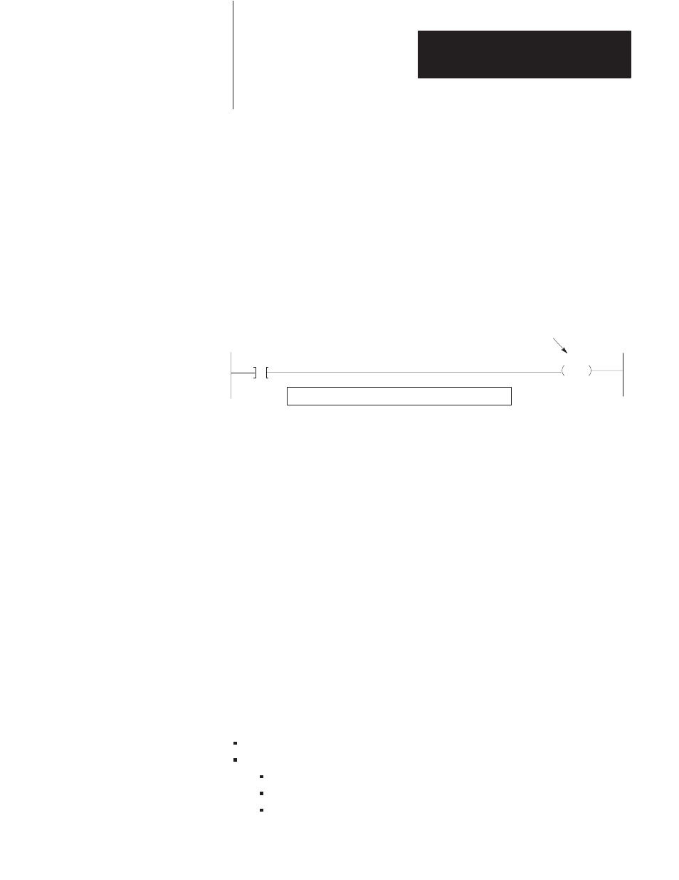
Figure 9.6
Optional Test Counter
CTU
057
03210
Start Bit
Insert between optional test rungs 3 and 4 if needed.
Increments to show continuous
sending of tested command message
Note that the counter value shown on the programming terminal may not
display the actual number of times a command has been sent, due to CRT
delay time. However, the purpose of the counter is to provide an
indication to the troubleshooter that the command is being continuously
executed, rather than to give an actual count of the number of times it is
executed.
Again, the use of these test rungs is optional, subject to the discretion of
the programmer. An advantage of these rungs is that they may be kept at
the end of the user program after start-up is completed. This enables use
of these rungs in subsequent troubleshooting or later testing, as when a
command rung is subsequently added to the communication zone of
program. Of course, these rungs can be removed after start-up is
completed, at the programmer’s option.
Recommended Documentation
For testing and troubleshooting command execution, the following
documentation should be available at each station processor:
Copy of the ladder-diagram program in the station processor
Completed forms giving the following information:
Communication adapter module switch settings
Listing of commands sent by the station
Listing of commands received by the station