Rockwell Automation 1771-KA2 Communication Adapter Module User Manual
Page 69
Status Words
Chapter 6
6-5
When a command cannot be carried out due to a user programming error
or a discrepancy in data handled by the communication adapter module,
an ERROR CODE may be written into a data table memory word. The
programmer selects the error code storage word and lists it in the header
rung of the communication zone of program. This word stores the most
recent error code written by the KA2.
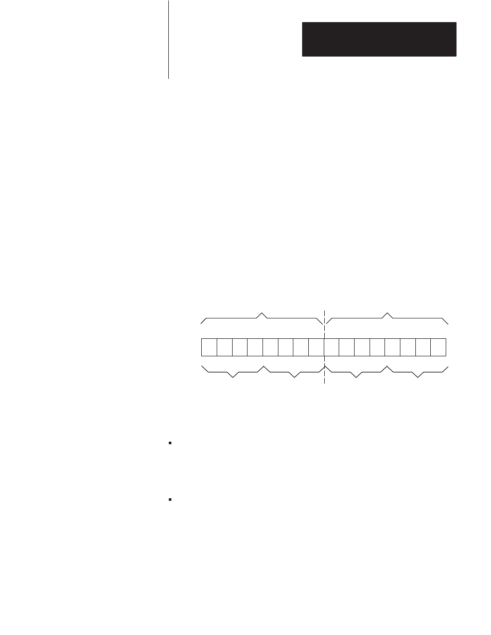
Figure 6.3 shows the structure of the ERROR CODE storage word. The
lower byte of this word (bits 00-07) stores any ERROR CODE entered by
the module. In this byte the ERROR CODE is represented as a 2-digit
binary coded decimal (BCD) number from 00-99. Table A.1 (Appendix
A) lists and describes these ERROR CODES.
Figure 6.3
ERROR CODE Word Format
17
16
15
14
13
12
11
10
07
06
05
04
03
02
01
00
0–9
0–9
0–9
0–9
Error Codes 00–99
in BCD Format
(Refer to Table 6–A)
Reference Number
(for codes 01–26)
Counter (for codes 30–99)
2–Digit Value:
ERROR CODES can be grouped as follows:
Codes 01-29 generally indicate that some programming error has been
detected in the communication zone of program. These codes are
intended to indicate errors or processor communication faults detected
at power-up. The program status indicator (PROG) may be on if one of
these codes is displayed.
Codes 30-99 generally indicate that some programming or hardware
related fault has been detected during attempts at communication
between stations. Codes 30-99 serve as diagnostic indicators after the
initial power-up checks of program have been completed.
A code in this 30-99 group is displayed whenever a REMOTE or LOCAL
FAULT bit is set ON.
Error Code Storage Word