Rockwell Automation 1747-SDN SLC 500 DeviceNet Scanner Module User Manual User Manual
Page 27
Publication 1747-UM655B-EN-P - June 2007
Planning Your Configuration and Data Mapping Your Devices 27
Mapping RediSTATION Input Data for an M1 File Data Table Read
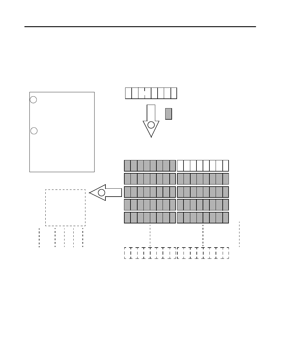
The following is an example of input data mapping for the
RediSTATION operator interface.
RediSTATION Input Byte
The bits for the RediSTATION
operator interfaces’s red and green
buttons are mapped into the
1747-SDN module’s M1 data table
file.
The M1 file is then transferred to
the SLC 500 processor’s input
data file.
What’s Happening?
Important: The 1747-SDN module only
makes the data file available for the
processor to read. The 1747-SDN
module does not move the data file to
the processor.
1
2
SLC 500 Processor
Input Data File
1
N7:0
N7:1
N7:2
N7:3
N7:4
N7:149
0000 0000 0000 00GR
0000 0000 0000 0000
0000 0000 0000 0000
0000 0000 0000 0000
0000 0000 0000 0000
0000 0000 0000 0000
R = Bit for Red Button (STOP)
G = Bit for Green Button (START)
1 byte
G R
1
= Unused Bits
1747-SDN Module M1 File Data Table
G R
Word 0
Word 1
Word 2
Word 3
Word 4
Up to
Word 61
2
1
This mapping is based upon the example in
chapters 4 and 6. The mapping for your system
may be different.
Example: The green START button from the
RediSTATION operator interface appears in the
SLC 500 processor’s input file at address
N7:0/1.
The red STOP button from the RediSTATION
operator interface appears in the SLC 500
processor’s input file at address N7:0/0.