Channel-status led indicators (green) – Rockwell Automation 1746-INT4 Thermocouple/MV Isolated/ User Manual User Manual
Page 67
Publication 1746-UM614B-EN-P - September 2007
Module Diagnostics and Troubleshooting 67
Channel-status LED Indicators (green)
The channel-status LED indicator operates with status bits in the
channel status word to indicate the following faults detected by the
module:
•
Invalid channel configuration
•
An open-circuit input
•
Out-of-range errors
When the module detects any of the following fault conditions, it
causes the channel-status LED indicator to blink and sets the
corresponding fault bit in the channel status word. Channel fault bits
(bits 12…15) and channel-status LED indicators are self-clearing when
fault conditions are corrected.
Open-circuit Detection (Bit 12)
The module tests all enabled channels for an open-circuit condition
each time it scans its inputs. Possible causes of an open-circuit
include:
•
broken thermocouple or CJC thermistor.
•
thermocouple or CJC thermistor wire cut or disconnected.
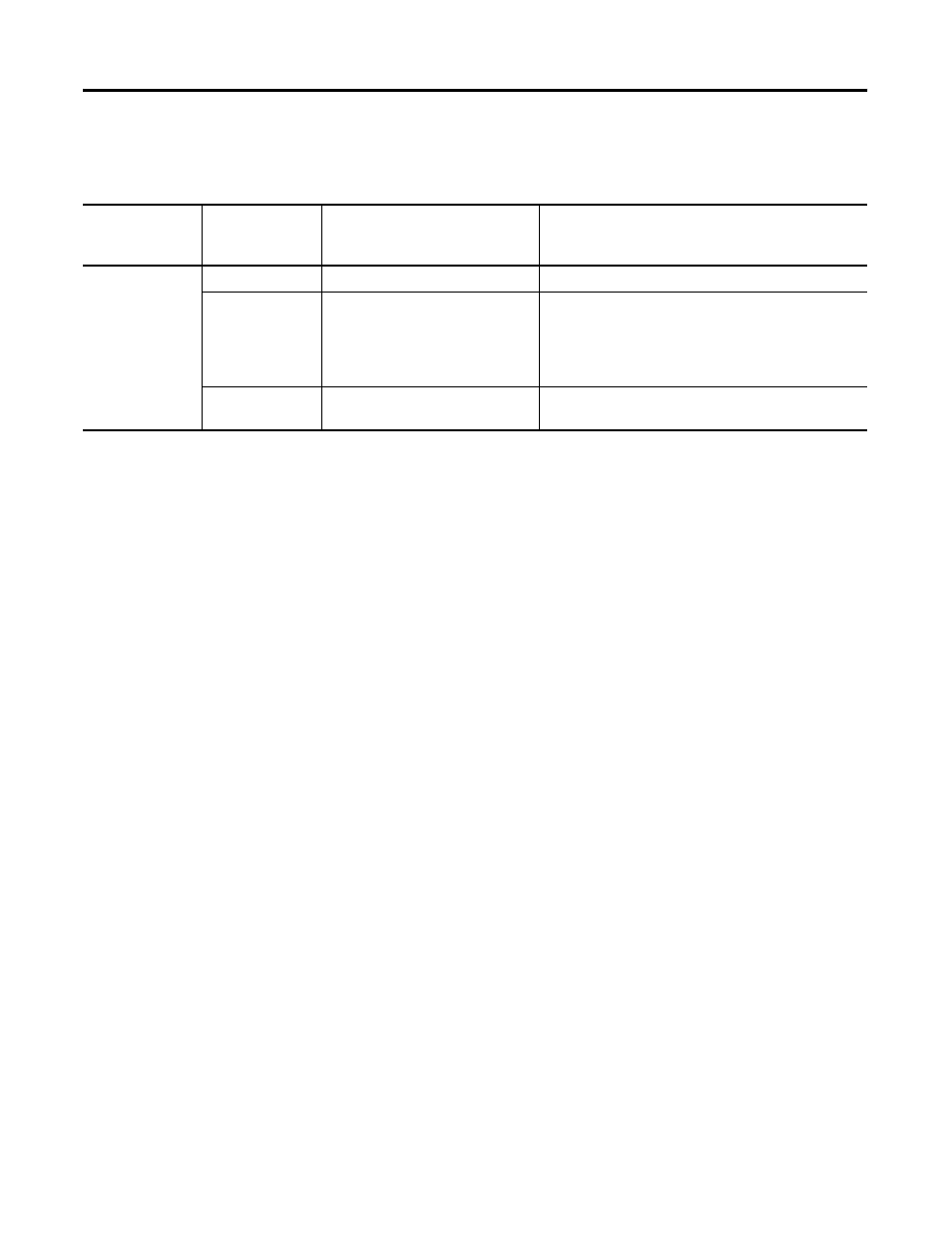
Module-status and Channel-status LED Indicators
If Module Status
LED Indicator is
And Channel
Status LED
Indicator is
Then
Take This Corrective Action
On
On
The channel is enabled.
No action required.
Blinking
The module detected:
open-circuit condition
under-range condition
over-range condition
channel configuration error.
Examine error bits in the status word:
if bit 12 = 1, the input has an open-circuit;
if bit 13 = 1, the input value is under-range;
if bit 14 = 1, the input value is over-range;
if bit 15 = 1, the configuration is invalid.
Off
The module is cycling power, or the
channel is disabled.
No action required.