Led indicators, Channel diagnostics, Led indicator troubleshooting tables – Rockwell Automation 1746-INT4 Thermocouple/MV Isolated/ User Manual User Manual
Page 66
Publication 1746-UM614B-EN-P - September 2007
66 Module Diagnostics and Troubleshooting
Channel Diagnostics
When a channel is enabled, the module checks for a valid
configuration. Then on each scan of its inputs, the module checks for
out-of-range and open-circuit fault conditions of its inputs including
the CJC thermistor.
When the module detects a failure of any channel diagnostic test, it
causes the channel status LED indicator to blink and sets the
corresponding channel fault bit (bits 12…15 of the channel status
word). Channel fault bits and LED indicators are self-clearing when
fault conditions are corrected.
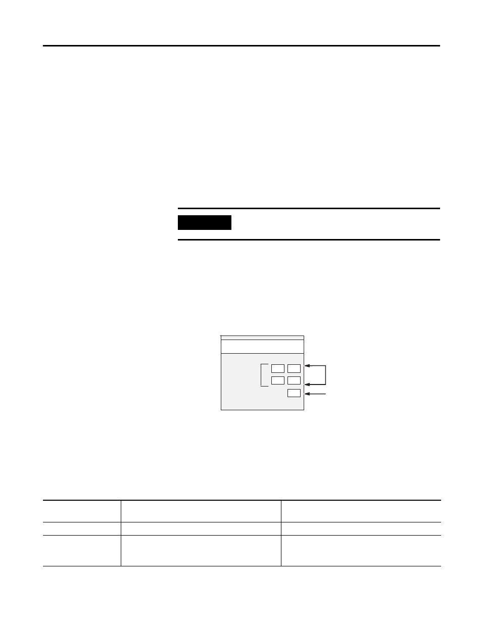
LED Indicators
The module has five status LED indicators.
•
Four channel-status LED indicators, numbered to correspond
with each channel
•
One module-status LED indicator
LED Indicators
LED Indicator Troubleshooting Tables
IMPORTANT
If you clear the channel enable bit, channel status bits are
reset.
0
1
2
3
INPUT
MODULE STATUS
CHANNEL
THERMOCOUPLE/mV
STATUS
ISOLATED
LED Indicators for Channels 0…3
LED indicator for Module Status
Module-status LED Indicator
If module status LED
indicator is
Then
Take this corrective action
On
The module is OK.
No action required.
Off
The module is turned off, or it detected a module fault. Cycle power. If the condition persists, call your local
distributor or Allen-Bradley customer service for
assistance.